


35
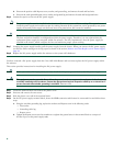
Step 6 To remove the SIP, first disconnect all cables from each SPA.
Step 7 Loosen the locking thumbscrews on both sides of the SIP.
Step 8 Slide the SIP out of the module slot. If you are removing a blank filler plate, pull the blank filler plate completely out
of the module slot.
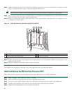
Remove the Shared Port Adapter
The shared port adapter ships installed. These instructions are provided for future use. Cabling information is included with the
specific shared port adapter documentation.
Step 1 Attach an ESD wrist strap between you and an unpainted chassis surface.
Step 2 Disconnect all cables from the shared port adapter.
Step 3 Before removing any shared port adapter, shut down the interface so that there is no traffic running through the shared
port adapter when it is removed.
Note Removing a shared port adapter while traffic is flowing through the ports can cause system disruption.
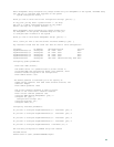
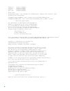
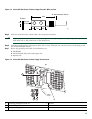
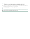
Step 4 Remove the shared port adapter from the chassis slot. Grasp the handle and pull the shared port adapter or blank shared
port adapter from the router.
Figure 16 Installing and Removing the Shared Port Adapter
Step 5 Locate the shared port adapter slot guides inside the Cisco ASR 1004 Router. They are near the top, and are recessed
about one-half inch.
S
T
A
T
U
S
S
TA
T
US
C
/
A
C/A
A/
L
A/L
3
3
S
P
A-
4X
OC3-P
OS
S
P
A-
4X
OC3-
P
OS
0
1
2
C
/
A
C
/A
S
TA
T
US
S
TA
T
US
0
A/
L
A
/
L
C
/
A
C/A
A
/
L
A
/
L
C
/
A
C/A
A
/
L
A
/
L
C
/
A
C/A
A
/
L
A
/
L
1
2
3
3
S
PA
-4X
O
C
3-
P
O
S
S
PA
-4X
O
C
3-
P
O
S
A
SR
10
00-SI
P
1
0
P
W
RST
A
T
U
S
S
TA
TU
S
S
T
A
T
U
S
C
/
A
C/A
A/L
A
/L
3
3
S
P
A-4
XO
C
3
-POS
S
P
A-
4
XOC
3
-POS
C/
A
S
TATUS
ST
A
T
U
S
0
A
/
L
C
/A
A/
L
C/A
A/
L
C
/
A
A
/
L
1
2
3
S
PA-
4
X
O
C
3
-
PO
S
A
S
R
10
0
0-S
I
P
10
P
W
RS
T
AT
U
S
S
PA-4
XOC
3
-PO
S
0
1
2
3
C
/
A
A
/L
C
/A
A
/L
C/A
A
/L
C/A
A
/L
281171