


15
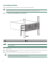
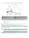
Step 3 Insert the AC power cable into the power supply inlet.
Step 4 Plug the power supply cable into the power source.
Step 5 The power supply LEDs light when power is supplied to the router.
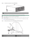
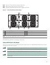
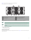
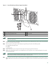
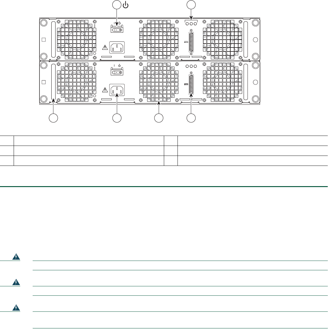
Figure 10 Cisco ASR 1004 Router AC Power Supply
Step 6 Turn the power supply Standby switch to On (|) position.
This completes the procedure for connecting AC-input power.
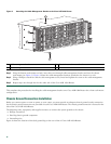
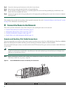
Connect DC Power to the Router
This section provides instructions for installing the DC power supply into the Cisco ASR 1004 Router. Read the safety warnings
and important notices before you begin.
Warning
Installation of the equipment must comply with local and national electrical codes.
Statement 1074
Warning
Never install an AC power module and a DC power module in the same chassis.
Statement 1050
Warning
When installing or replacing the unit, the ground connection must always be made first and disconnected last.
Statement 1046
1
AC power supply Standby switch
4
AC power supply fan
2
AC power supply LEDs
5
AC power inlet
3
DB-25 Alarm connector
6
AC power supply handle
280184
OUTPUT INPUT
FAIL
OK OK
FAN
100V-240V~ 12A-5A
50-60Hz
ALARMS
60V
1A MAX
OUTPUT INPUT
FAIL
OK OK
FAN
100V-240V~ 12A-5A
50-60Hz
ALARMS
60V
1A MAX
1 2
34
6
5