


24-12
ATM and Layer 3 Switch Router Software Configuration Guide
OL-1911-05
Chapter 24 Configuring ATM Router Module Interfaces
Configuring LECs on ATM Router Module Interfaces (Catalyst 8540 MSR)
Example
The following example shows how to configure two LECs on an ATM router module interface:
Switch# configure terminal
Switch(config)# interface atm 1/0/0.4 multipoint
Switch(config-subif)# ip address 40.0.0.1 255.0.0.0
Switch(config-subif)# lane client ethernet VLAN4
Switch(config-subif)# exit
Switch(config)# interface atm 1/0/0.5 multipoint
Switch(config-subif)# ip address 50.0.0.1 255.0.0.0
Switch(config-subif)# lane client ethernet VLAN5
Switch(config-subif)# exit
Switch(config)# router ospf 1
Switch(config-router)# network 40.0.0.0 0.255.255.255 area 0
Switch(config-router)# network 50.0.0.0 0.255.255.255 area 0
For more information on configuring LECs on ATM router module interfaces, see Chapter 13,
“Configuring LAN Emulation.” For a detailed description of LANE and its components, refer to
Cisco IOS Switching Services Configuration Guide: Virtual LANs.
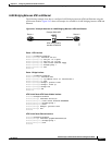
LEC Configuration Examples
The examples in this section show how to configure LANE clients (LECs) on networks with two routers
and one Catalyst 8540 MSR. For detailed information on configuring the LANE server (LES), LANE
configuration server (LECS), and broadcast-and-unknown server (BUS), see Chapter 13, “Configuring
LAN Emulation.”
Caution For performance reasons, avoid configuring the LANE server components on ATM switch routers.
Instead, configure the LANE server components on a router such as a Cisco 7500 series router or a
Catalyst 5500 router with a LANE module installed.
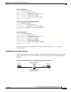
LANE Routing Over ATM
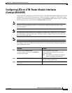
The following example shows how to configure LANE routing over ATM using the ATM router module.
Figure 24-3 shows an example of a network for LANE routing over ATM.
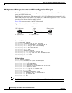
Figure 24-3 Example Network for LANE Routing over ATM
Router 1 Router 2
Catalyst 8540 MSR
ATM router module
Interface ATM 2/0/0
ATM 2/0 ATM 3/0
45158