


24-13
ATM and Layer 3 Switch Router Software Configuration Guide
OL-1911-05
Chapter 24 Configuring ATM Router Module Interfaces
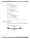
Configuring LECs on ATM Router Module Interfaces (Catalyst 8540 MSR)
Router 1 ATM Interface
Router1# configure terminal
Router1(config)# interface atm 2/0
Router1(config-if)# ip address 1.0.0.1 255.0.0.0
Router1(config-if)# atm pvc 1 0 5 qsaal
Router1(config-if)# atm pvc 2 0 16 ilmi
Router1(config-if)# lane client ethernet happy
Router1(config-if)# end
Router1#
ATM Switch Router ATM Router Module Interface
Switch# configure terminal
Switch(config)# interface atm 2/0/0
Switch(config-if)# ip address 1.0.0.2 255.0.0.0
Switch(config-if)# lane client ethernet BACKBONE
Switch(config-if)# end
Switch#
Router 2 ATM Interface
Router2# configure terminal
Router2(config)# interface atm 3/0
Router2(config-if)# ip address 1.0.0.3 255.0.0.0
Router2(config-if)# no ip mroute-cache
Router2(config-if)# atm pvc 1 0 5 qsaal
Router2(config-if)# atm pvc 2 0 16 ilmi
Router2(config-if)# no atm ilmi-keepalive
Router2(config-if)# lane client ethernet BACKBONE
Router2(config-if)# end
Router2#
For detailed information on configuring LANE clients (LECs), see Chapter 13, “Configuring
LAN Emulation.”
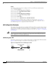
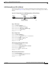
LANE Routing from ATM to Ethernet
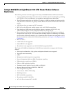
The following example shows how to configure LANE routing from ATM to Ethernet using the ATM
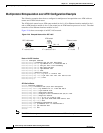
router module. Figure 24-4 shows an example of a LANE network for LANE routing from ATM to
Ethernet.
Figure 24-4 Example Network for LANE Routing from ATM to Ethernet
Router 1 Router 2
Catalyst 8540 MSR
ATM router module
Interface ATM 2/0/0
ATM 2/0
GE 9/0/0
GE 9/0/0
45222