


24-24
ATM and Layer 3 Switch Router Software Configuration Guide
OL-1911-05
Chapter 24 Configuring ATM Router Module Interfaces
Configuring Bridging
Configuring Bridging
All PVCs configured on ATM router module interfaces are used for bridging.
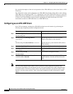
To configure bridging on an ATM router module interface, use the following commands, beginning in
global configuration mode:
Example
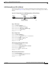
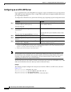
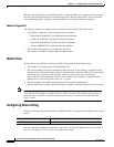
The following example shows how to configure bridging on a Catalyst 8540 MSR with a Fast Ethernet
interface module in slot 0, an ATM interface module in slot 1, and an ATM router module in slot 3.
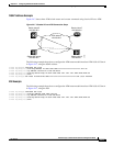
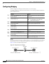
Figure 24-8 shows an example bridging network.
Figure 24-8 Example Network for Bridging
Command Purpose
Step 1
Switch(config)# interface atm card/subcard/port
Switch(config-if)#
Specifies the interface on the ATM router module
to configure.
Step 2
Switch(config-if)# atm pvc 2 vci interface atm
card/subcard/port vpi
Configures a PVC.
Note The VPI number on the ATM router
module interface must be 2.
Step 3
Switch(config-if)# bridge-group number Assigns the interface to a bridge group.
Step 4
Switch(config-if)# end
Switch(config)#
Returns to global configuration mode.
Step 5
Switch(config)# interface fastethernet
card/subcard/port
Switch(config-if)#
Specifies the Fast Ethernet interface to configure.
Step 6
Switch(config-if)# no cdp enable Disables Cisco Discovery Protocol on the
interface.
Step 7
Switch(config-if)# bridge-group number Assigns the interface to a bridge group.
Step 8
Switch(config-if)# end
Switch(config)#
Returns to global configuration mode.
Step 9
Switch(config)# bridge number protocol ieee Specifies the IEEE 802.1D Spanning-Tree
Protocol for the bridge group.
Cisco 7500 router A
ATM switch
router
Cisco 7500 router B
IF = atm 1/0/0
10.10.10.2
IF = atm 0
MAC addr = 0000.0CAC.BE94
10.10.10.1
IF = e0
MAC addr = 0060.3E59.C63C
IF = fa 0/0/0
38492