


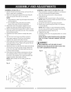
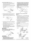
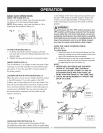

BLADEGUARDASSEMBLY(FIG. J, K, L)
1. Set the blade to maximum height and the tilt to zero
degrees on the bevel scale with the hand wheels.
Lock the blade bevel lock knob.
2. Place the spring washer (2), flat washer (3), external
tooth lock washer (4) onto the blade guard mounting
bolt (1)(Fig. J).
3. Insert bolt and washer assembly through splitter
bracket (5). 5
4.
5.
Fig. J 4
2
Blade guard
and splitter ass'y
3
11
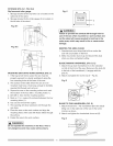
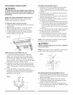
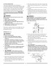
Place the oval washer (6) on the pivot rod (7) (Fig. K).
Install the blade guard and splitter and bracket
assembly (8) into the rear of the saw table. Thread
the bolt (1) into the internally threaded pivot rod until
snug.
Fig. K
7 6
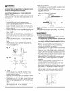
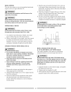
6. Lift blade guard arm (9) up and using a straight edge,
align the blade guard and splitter (10) with the saw
blade (11) (Fig. L).
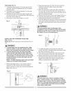
7. Shift the splitter bracket assembly to right or left until
parallel alignment to the blade is achieved.
8. When the splitter is properly aligned with the saw
blade, tighten the bolt securely.
NOTE: The splitter bracket must always be correctly
aligned so the cut workpiece will pass on either side
without binding or twisting.
WARNINGI
See Fig. K-1 fiat washer (11) must be under
knob (12). NOTE: Be sure to tighten knob very tight
and periodically check tightness.
Fig. K=I "_
[A WARNINGI
• AVOID KICKBACKS (FIG. L)
(Work thrown back towards you) by keeping
the blade sharp, the rip fence parallel to the
saw blade and by keeping the splitter, anti-
13
kickback pawls and guards in place, aligned and
functioning. Do not release work before passing
it completely beyond the saw blade. Do not rip
work that is twisted, warped or does not have a
straight edge to guide it along the fence. Do not
attempt to reverse out of a cut with the blade
running.
Improper splitter alignment can cause "kickback"
and serious injury.
Fig. L Anti-Kickback Pawl 9 I1
1
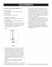
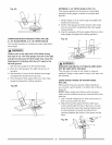
INSTALLING THE TABLE EXTENSION FENCE
(FIG. M, M-l)
NOTE:
A. For right ripping a 10 in.- 14 in. wide workpiece, the
right extension fence has to be installed in the IN-RIP
position (Fig. M). For left ripping a 11 in. - 16 in. wide
workpiece, the left extension fence has to also be
installed in the IN-RIP position. Raise the fence to a
position that just clears the table surface and secure
in place using lock knobs (1) for IN-RIP position.
B. For right ripping a 14 in. - 24 in. wide workpiece, the
right extension fence has to be installed in the OUT-
RiP position (Fig. M-l). For left ripping a 16 in. - 24
in. wide workpiece, the left extension fence has also
to be installed in the OUT-RIP position.
To install fence:
1. Install the lock knobs (1) on the aluminum extension
table.
2. Place the table extension fence (2) on the aluminum
extension table.
3. Raise the fence to the desired location and height
and tighten the lock knobs (1).
Fig. M ___ 2_1
Fig. M-f