


[A WARNINGI
To avoid injury from an accidental start, make sure
the switch is in the OFF position and the plug is not
connected to the power source outlet.
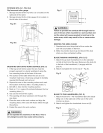
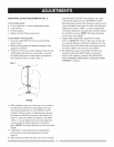
ADJUSTING THE 90° AND 45 ° POSITIVE STOPS
(FIG. Q, Q-f, R)
Your saw has positive stops that will quickly position the
saw blade at 90 ° to the table. Make adjustments only if
necessary.
900 (0°) Stop
1. Disconnect the saw from the power source.
2. Turn the blade elevation handwheel and raise the
blade to the maximum elevation.
3. Loosen the blade bevel lock knob (2) and move the
blade to the maximum vertical position, then tighten
the lock knob (2).
4. Place a combination square on the table and against
the blade (1) to determine if the blade is 90° to the
table. (Fig. Q-1 )
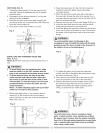
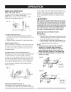
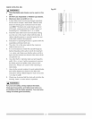
5. tf the blade is not 90° to the table, loosen the two set
screws (4), located on the collar (5) underneath the
table saw, (Fig. R) with the hex key, and back off the
collar.
6. Loosen the bevel lock knob. Turn the blade tilting
handwheel to move the blade until it is 90° to the
table.
7. Adjust the collar (5) so it contacts the bracket (3)
when the blade is 90° to the table. Tighten the two
set screws (4). (Fig. R)
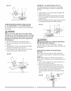
Fig, Q
Fig. Q-1
90° 45 °
45 ° Stop
1. With the blade in the upright 90° position, loosen
the bevel lock knob and move the blade to the 45°
position as far as it will go.
2. Place the combination square on the table as shown
in Fig. Q-1 to check if the blade is 45° to the table.
3. tf the blade is not 45° to the table, loosen the two set
screws (4), located on the collar (5) underneath the
table saw, (Fig. R) with the hex key, and back off the
collar.
4. Tighten the bevel lock knob and secure the screw (4)
until resistance is felt. Do not overtighten.
BLADE TILT POINTER
1. When the blade is positioned at 90°, adjust the blade
tilt pointer to read 0° on the scale.
2. Loosen the mounting screw, position pointer over 0°
and tighten the screw.
NOTE: Make a trial cut on scrap wood before making
critical cuts. Measure for exactness.
Fig. R 4 _ 450
5
3
3 4 5
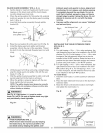
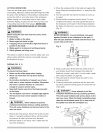
BLADE PARALLEL TO THE MITER GAUGE GROOVE
(FIG. S, T)
This adjustment was made at the factory, but it should
be rechecked and adjusted if necessary.
IA wAR.I.GI
To prevent personal injury:
• Always disconnect plug from the power source
when making any adjustments.
• This adjustment must be correct or accurate cuts
can not be made. Also, inaccurate adjustment
can result in kickback and serious personal injury.
1. Remove the safety switch key and unplug the saw.
2. Remove the blade guard for this procedure but
reinstall and realign after adjustment.
3. Raise the blade to the highest position and set at the
0° angle (90 ° straight up).
4. Select and mark, with a felt tip maker, a blade tooth
having a "right set" and rotate the blade so the marked
tooth is Y2in. above the table at the front of the saw.
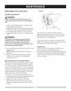
5. Place the combination square base (1) into the right
side miter gauge groove (2). (Fig. S)
6. Adjust the rule so it touches the front marked tooth
and lock ruler so it holds its position in the square
assembly.
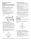
7. Rotate the blade bringing the marked tooth to the
rear and about 1/2 in. above the blade.
8. Carefully slide the combination square to the rear
until the ruler touches the marked tooth.
9. tf the ruler touches the marked tooth at the front and
rear position, no adjustment is needed at this time.
tf not or the base of the rule is no longer parallel
with the edge of the miter gauge groove, perform
adjustment procedure described in next section.
Fig, S
15