


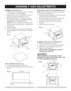
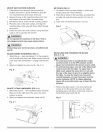

MOUNTSAWONWORKSURFACE
1. tfthestandwillnotbeused,thesawmustbe
properlysecuredtoasturdyworkbenchusingthe
fourmountingholesat thebaseofthesaw.
2. Squarethesawonthemountingsurfaceandmark
thelocationofthefour3/8in.mountingholes.
3. Drillthefour3/8in.holesintothemountingsurface.
4. Placethesawontheworksurface,andalignthe
mountingholesofthesawwiththosedrilledthrough
thesurface.
5. Fastenthesawtotheworksurface.Usinghardware
suchas1/2in.lugboltswithwasher.
[A WAR"ING1
Do not operate this machine on the floor. This is
very dangerous and may cause serious injury.
[A WARNINGI
Always keep your work area clean, uncluttered and
well lit.
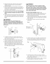
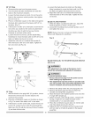
BLADE RAISING HANDWHEEL (FIG. C)
1. Attach the up - down handwheel (1) to the elevation
rod (2) at the front of the saw. Make sure the slots (3)
in the hub of the handwheel (1) engage with the pins
(4).
2. Attach and tighten the dome nut (5 - Fig. C-1).
Fig. C
1
BLADE TILTING HANDWHEEL (FIG. C=f)
1. Attach the bevel 0° - 45° handwheel (6) to the blade
tilting rod on the right side of the saw in the same
manner as above.
2. Attach and tighten the handwheel dome nut (5).
Fig. C=1
{
//
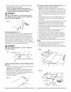
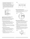
RIP FENCE (FIG. D)
1. Lift upward on the rip fence handle (1) so the rear
holding clamp (2) is fully extended.
2. Place the rip fence on the saw table, and attach the
set plate (3) under the fence handle (1) to the rail
first.
3. Push down on the fence handle (1) to lock.
Fig. D
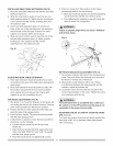
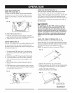
INSTALLING AND CHANGING THE BLADE
(FIG. E, F, G)
I,_ WARNING I
* To avoid injury from an accidental start, make
sure the switch is in the OFF position and the
plug is not connected to the power source outlet.
,, To avoid serious injury, the rear of the table insert
must be level with the table. To adjust rear of
table insert, adjust the screw (3) in or out until
the rear of the insert is level to or slightly above
the table. To raise the insert, turn the screw
counterclockwise, to lower the insert, turn the
screw clockwise. NOTE: A rubber adjusting
spacer (4) is provided under rear of insert for this
purpose.
1.
Remove the table insert (1) by removing the two
screws (2, 3). Be careful not to lose the rubber
adjusting spacer (4) that is on the back screw (3)
beneath the table insert (Fig. E).
Fig. E
_ _======t
_3
8---2
11