


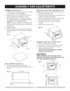
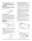
2. Raisethebladearbor(4-Fig.F)tothemaximum
heightbyturningthebladeraisinghandwheel
counterclockwise.
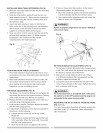
3. Placetheopen-endwrench(8)jawsontheflatsof
thesawarbortokeepthearborfromturning(Fig.G)
andplacethebox-endwrench(9)onthearbornut
(5),andturncounterclockwise.
4. Removethearbornut(5)andouterflange(6-Fig.F).
5. InstallthesawbladeontothearborwiththeBLADE
TEETHPOINTINGTOWARDTHEFRONTOFTHE
SAW.
6. Installtheflange(6)againstthebladeandthreadthe
arbornut(5)asfaraspossiblebyhand.Ensurethat
thebladeisflushagainsttheinnersideof theblade
flange.
[A WARNINGI
To avoid possible injury and damage to the
workpiece, be sure to iNSTALL THE BLADE WiTH
THE TEETH POiNTiNG TOWARD THE FRONT OF
TABLE in the direction of the rotation arrow on the
blade guard.
Fig. F
4 7
6 5
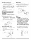
7. To tighten the arbor nut, (5) place the open-end
wrench (8) on the flats of the saw arbor to keep the
arbor from turning (Fig. G).
8. Place the box-end wrench (9) on the arbor nut (5),
and turn clockwise (to the rear of the saw table).
9. Replace the blade insert in the table recess, insert
the screws through the front and rear holes and
tighten remembering the rubber adjusting spacer
(4-Fig. E) under the rear of the insert and leveling the
rear of the insert to the table.
Fig. G
8 --
IA WARNING!
To avoid injury from a thrown workpiece, blade
parts, or blade contact, never operate saw without
the proper insert in place. Use the original installed
insert for all through=sawing operations except dado
cuts. A special dado insert plate must be installed
when using a dado blade.
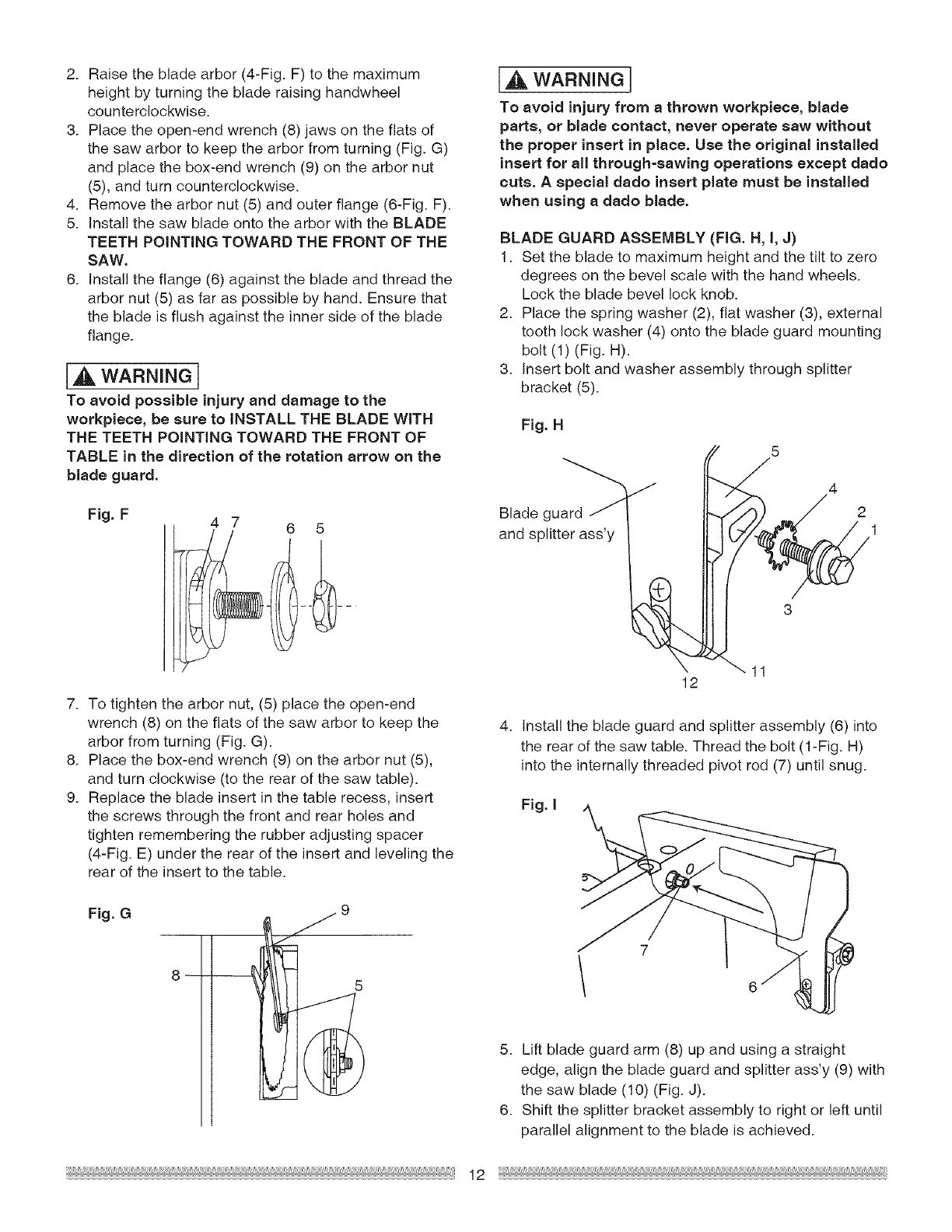
BLADE GUARD ASSEMBLY (FIG. H, I, J)
1. Set the blade to maximum height and the tilt to zero
degrees on the bevel scale with the hand wheels.
Lock the blade bevel lock knob.
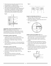
2. Place the spring washer (2), flat washer (3), external
tooth lock washer (4) onto the blade guard mounting
bolt (1) (Fig. H).
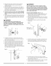
3. Insert bolt and washer assembly through splitter
bracket (5).
Fig. H
Blade guard _
and splitter ass'y
J
12
5 4
1
4. Install the blade guard and splitter assembly (6) into
the rear of the saw table. Thread the bolt (1-Fig. H)
into the internally threaded pivot rod (7) until snug.
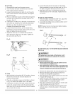
Fig. I
5. Lift blade guard arm (8) up and using a straight
edge, align the blade guard and splitter ass'y (9) with
the saw blade (10) (Fig. J).
6. Shift the splitter bracket assembly to right or left until
parallel alignment to the blade is achieved.
12