


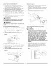
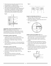
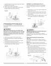

7. Rotatethebladebringingthemarkedtoothtothe
rearandaboutYzin. above the blade.
8. Carefully slide the combination square to the rear
until the ruler touches the marked tooth.
9. tf the ruler touches the marked tooth at the front and
rear position, no adjustment is needed at this time.
tf not or the base of the rule is no longer parallel
with the edge of the miter gauge groove, perform
adjustment procedure described in next section.
Fig. R
Fig. S
2
1 4
3
,,_,============================
j2
1
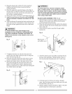
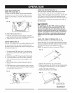
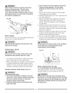
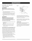
BLADE TILTING INDICATOR (FIG. T)
1. When the blade is positioned at 90°, adjust the blade
tilt pointer to read 0° on the scale.
2. Remove the magnifier, position the pointer over 0°
and replace the magnifier.
Fig. T
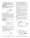
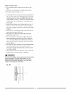
ADDITIONAL BLADE ADJUSTMENTS (FIG. S)
NOTE: The adjusting lock nuts are 8 ram.
The adjusting mechanism is located above the blade
height adjusting hand wheel under the tabletop, tf the
front and rear measurements are not the same.
If the blade is partial to right aide:
1. Loosen the two lock nuts (1) and turn the left
adjustment screw (2) counterclockwise, then adjust
the right side adjustment screw (3) clockwise.
2. Remeasure, as described in steps 4 to 9 in the
prior section.
3. When alignment is achieved, turn the left adjustment
screw (2) until it touches the pivot rod (4) then tighten
both lock nuts (1).
if the blade is partial to left aide:
1. Loosen the two lock nuts (1) and turn the right
adjustment screw (3) counterclockwise, then adjust
the left side adjustment screw (2) clockwise.
2. Remeasure, as described in steps 4 to 9 in the
prior section.
3. When alignment is achieved, turn the right
adjustment screw (3) until it touches the pivot rod (4)
then tighten both lock nuts (1).
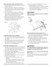
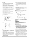
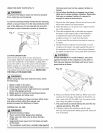
MITER GAUGE ADJUSTMENT (FIG. T=I)
1. Loosen the lock handle (1) to allow miter body (2) to
rotate freely (Fig. T-1). Position the miter body at
90° so the positive detent secures its position.
Tighten the lock handle to hold the miter body in
position.
2. tf the pointer (3) requires adjustment, loosen the
screw under the pointer with a hex key. Adjust the
pointer to 90° on the scale then firmly tighten the
adjustment screw.
3. To change angles on miter gauge, loosen the lock
handle (1) and rotate the miter body to desired angle
as indicated by the scale. Secure in position by
tightening the lock handle.
Fig. T-1
2
1
3
16