


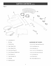

Fig. 16
\
4, Place the second locking band through all the loops
of the collection bag, similar to the filter bag,
5,
Place the collection bag over the lower lip of the
drum, Pull up on the retaining clips and insert cop
lection bag underneath each retaining clip, Make
certain the locking band is positioned in the lower
recessed channel of the drum and fasten clamp
securely to drum,
2,
D
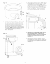
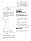
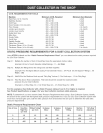
Slide the lower support rod (C) onto the end of
the upper support rod (B), Raise the assembled
support rod with filter bag attached and place the
end of the lower support rod into the hobs of the
U=bracket (D), The flared end of lower support
rod will prevent the rod from sliding through the
U=bracket, See figure 16,
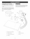
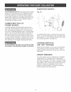
FLEXIBLE HOSE TO
iNTAKE PORT ASSEMBLY
MAKE CERTAIN THE DUST COLLECTOR
DISCONNECTED FROM THE POWER SOURCE.
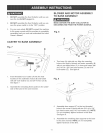
IMPORTANT: When connecting an intake hose to one
or both intake ports, DO NOT REMOVE THE INTAKE
PORT CAPS FROM THE INTAKE PORTS, Slide the
collar further back the intake port when attaching a
hose,
1, To attach the 4-inch flexible hose to one of the
intake ports, pull the intake port cap from the intake
port, Slide the collar of the intake port cap further
back the intake port and let the cap hang from the
intake port,
2, Place 4=inch hose clamp over 4=inch flexible hose,
Slide hose over one intake port opened Step 1
above and tighten hose clamp,
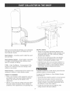
3, if you wish to use the second intake port, you
should purchase a second 4=inch flexible hose and
4=inch hose clamp and repeat Steps 1 and 2 above,
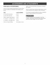
See your nearest Sears Hardware Department or Sears
Power and Hand Tool Catalog for other accessories,
Use only accessories recommended for this Dust
Collector, Using other accessories may cause serious
injury and cause damage to the Dust Collector,
G F E
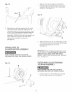
3,
insert locking band (E) through all the loops of filter
bag (F), Position the open end of the filter bag over
the top lip of the drum, Make certain the locking
band is positioned in the upper recessed channel of
the drum and fasten clamp (G) securely to drum,
See figure 17,
14