


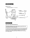
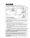
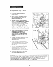

INSTALLING AND REMOVING THE CUTTING BIT (Figs. 3, 4 and 4a)
X,,./ _,,. Nut coHet
Spindle Lock
Fig. 3
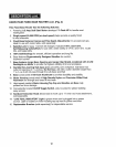
INSTALLING THE CUTTER BIT
1o Turn motor off and unplug from power source,
2. Remove motor housing from fixed base.
I
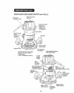
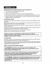
F, 4
Fig. 4a _._ Cutters
NOTE: See instructions on removing and installing the motor housing from the
fixed base on pages 17.
3. Set the motor upside down on its top cap, with collet/nut pointing Upo
4., Press spindle lock button to engage and lock the spindle shaft and collet/nut, (Fig. 3),
5o Place the wrench on the collet/nut and turn counter-clockwise and loosen collet/nut
slightly to accept cutter bit shank.
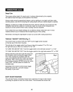
6, Insert cutter bit shank into collet!nut assembly as far as it will go, then back the shank
out until the cutters are approximately 1/8 to 1/4-inch away from the face of the
collet/nut (Fig. 4, 4a)
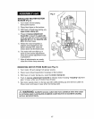
7, With cutter bit inserted and spindle lock button pressed in engaging shaft, place wrench
on colletinut and turn clockwise until router cutter bit and collet/nut are firmly tightened.
Z_ WARNING: TIGHTEN COLLET/NUT SECURELY to prevent the cutter bit
from slipping. If the collet/nut is not securely tightened, the cutter bit may detach
during use, causing serious personal injury
NOTE: To ensure proper gripping of cutter bit shank and minimize run-out, the 1
shank of the cutter bit must be inserted into the coitet/nut at least 5/8-inch.
J
I Z_ CAUTION: To prevent damage to tool, do not tighten cotlet/nut without ]
a cutter bit installed.
/
15