


Owner's Manual Model No. 875.199810 Owner's Manual Model No. 875.199810
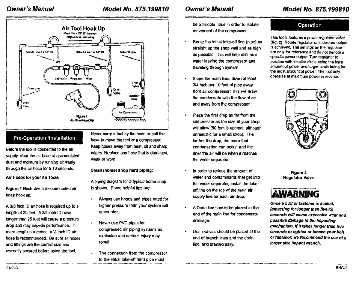
Air Tool Hook Up
Before the toolis connected tothe air
supply, dear the air hose of accumulated
dust and moisture by runn{ng airfreely
through the air hose for 5-10 seconds.
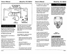
Air HoseS for yourAir Tools
Figure 1 Illustrates a recommended air
hose hook up.
A 3/8 inch ID air hose is required up to a
length of 25 feet. A 3/8 inch ID hose
longer than 25 feet willcause a pressure
drop and may impede performance. If
more length is required, a ½ inch ID air
hose is recommended. Be sure all hoses
and fittings are the correct size and
correctly secured before using the tool.
Never carry a tool by the hose or pu[Ithe
hose tomove the tool or a compressor.
Keep hoses away from hea_, oiland sharp
edges. Replace any hose thai is damaged,
weak or worn.
Small (home) shop hard piping:
A piping diagram for a typical home shop
is shown. Some helpful tips are:
• Always use hosesandpipesratedfor
higherpressurethanyourSystemwill
encounter,
Never use PVC pipes for
compressed air piping systems as
explosion and serious injury may
result.
The connection from the compressor
to the initial take-off herd pipe must
be a flexible hose in order to isolate
movement of the compressor.
Route the initial take-off line (pipe) as
straight up the shop wall and as high
as possible, This will help minimize
water leaving the compressor and
traveling through system
Slope the main lines down at least
3/4 inchper 10 feet of pipe away
from air compressor; this will draw
the condensate with the flow of air
and away from the compressor.
Place the first drop as far from the
compressor as the size of your shop
wiltallow (50 feet is optimal, although
unrealistic for a small shop). The
further the drop, the more that
condensation can occur, and the
dher the air will be when it reaches
the water separator.
In older to reduce the amount of
water and contaminants that get into
the water separator, install the take-
offline on the top ofthe main air
supply line for each air drop,
A Drain line should be placed at the
end of the main line for condensate
drainage.
Drain valves should be placed at the
end of branch lines and the drain
line, and drained daily.
This toolsfeatures a powerregulator ,a_zlve
(fig. 2). Rotate regulatoruntiJdesired output
is achieved. The settingson the regu!etor
are onlyfor reference and donot denote a
specific power output.Turn regulator to
position with smaller circlebeing the least
amount ofpower end largef circle being/or
the most amount of power, The toolonly
operates at maximum powerin reverse.
Figure 2
Regulator Valve
•ARNINGI
Once ,_bolt Or Pastener is seated,
Impacting for longer than five (5)
seconds will cause excessive wear and
possible damage to the Impacfing
mechanism, flit takes longer than five
seconds to tighten or loosen your bolt
or fastener, we recommend the use of a
larger size impact wrench.
ENG-6 ENG-7