


GUARD t
Jtmay be necessary to brace or support one
end of the outfit when attaching the wheels
because the air compressor will have a
tendency to tip.
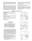
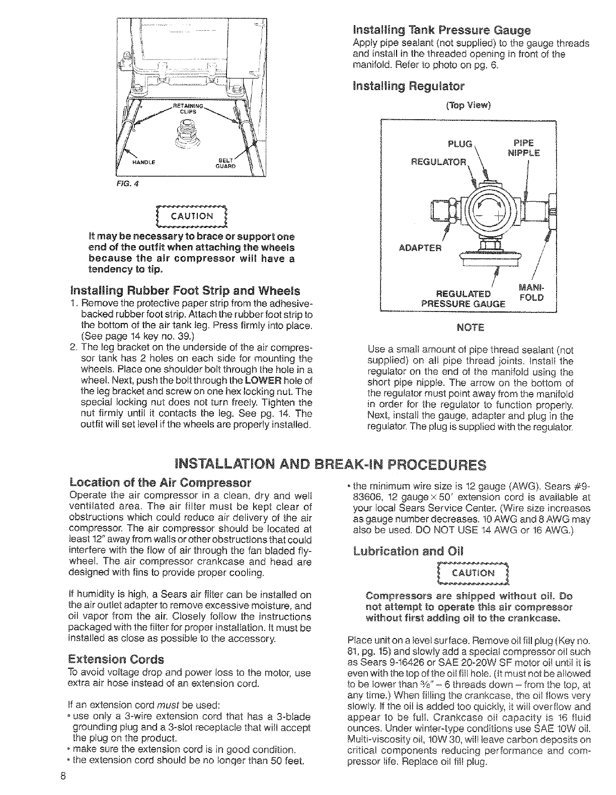
mnstagJiag Rubber Foot Strip and Wheels
t. Remove the protective paper strip from the adhesive-
backed rubber foot strip. Attach the rubber foot strip to
the bottom of the air tank leg, Press firmly into place.
(See page 14 key no. 39.)
2. The leg bracket on the underside of the air compres-
sor tank has 2 holes on each side for mounting the
wheels. Place one shoulder bolt through the hote in a
wheel. Next, push the bolt through the LOWER hole of
the leg bracket and screw on one hex locking nut. The
special locking nut does not turn freely. Tighten the
nut firmly until it contacts the leg. See pg. 14. The
outfit will set level if the wheels are properly installed.
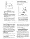
_nataHing Tank Pressure Gauge
Apply pipe sealant (not supplied) to the gauge threads
and install in the threaded opening in front of the
manifold. Refer to photo on pg. 6_
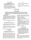
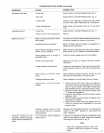
InstatSing Regulator
(Top View}
PLUG PiPE
N_PPLE
REGULATOR
ADAPTER _._
MAN_=
REGULATED FOLD
PRESSURE GAUGE
NOTE
Use a small amount of pipe thread seatant (not
supplied} on ali pipe thread joints. Install the
regulator on the end of the manifold using the
short pipe hippie. The arrow on the bottom of
the regulator must point away from the manifold
in order for the regulator to function properly'.
Next, install the gauge, adapter and plug in the
regulator. The ptug is supplied with the regulator.
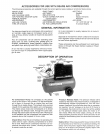
NSTALLATJON AND BREAK= N PROCEDURES
Location of the Air Compressor
Operate the air compressor in a clean, dry and well
ventilated area. The air filter must be kept clear of
obstructions which could reduce air delivery of the air
compressor. The air compressor should be Iocated at
least 12" away from wails OFother obstructions that could
interfere with the flow of air through the fan bladed fly-
wheel. The air compressor crankcase and head are
designed with fins to provide proper cooling.
If humidity is high, a Sears air filter can be insta!led on
the air outlet adapter to remove excessive moisture, and
oil vapor from the air. Closely foilow the instructions
packaged with the filter for proper installation. _tmust be
installed as close as possible to the accessory.
Extension Cords
To avoid voltage drop and power loss to the motor, use
extra air hose instead of an extension cord,
tf an extension cord must be used:
ouse only a 3-wire extension cord that has a 3-blade
grounding piug and a 3-slot receptacle that wilt accept
the plug on the product.
omake sure the extension cord is in good condition.
• the extension cord should be no longer than 50 feet.
° the minimum wire size is t2 gauge (AWG}. Sears #9-
83606, 12 gauge x 50' extension cord is available at
your local Sears Service Center. (Wire size increases
as gauge number decreases. 10AWG and 8 AWG may
also be used. DO NOT USE !4 AWG or 16 AWG.)
Lubrication and OH
Compressors are shipped without oil Do
not attempt to operate this air compressor
without first adding oi_ to the crankcaaeo
P!ace unit on a levet surface. Remove oil fill plug (Key no.
81, pg. 15) and slowly add a speciat compressor oil such
as Sears 9-16426 or SAE 20_20W SF motor oil until it is
even with the top of the oi! fill hole. (it must not be aliowed
to be Iower than 3/8"- 6 threads down - from the top, at
any time.) When ill!rig the crankcase, the oil flows vary
slowly. If the oil is added too quickly, it will overflow and
appear to be full. Crankcase oiI capacity is 16 fad
ounces. Under winter-type conditions use SAE 10W oil.
Multi-viscosity oil, 10W 30_witl teave carbon deposits on
critical components reducing performance and com-
pressor iife. Reptace oil fill plug.
8