


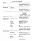
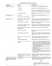
PressureSwitch:Thepressureswitchautomatically
startsthemotorwhenthesirtankpressuredropsbelow
thefactoryset"cat-in"pressure,itstopsthemotorwhen
theairtankpressurereachesthefactoryset"cut-out"
pressure.
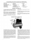
Regumstor:The air pressure coming from the air tank is
controlled by the regulator knob. Turn the knob
clockwise to increase pressure and counterclockwise to
decrease pressure. To avoid minor readjustment after
making a change in pressure setting, always approach
the desired pressure from a lower pressure. When
reducing from a higher to a !ower setting, first reduce to
some pressure tess than that desired, then bring up to
the desired pressure. Depending on the air requirements
of each particular accessory, the outlet regulated air
pressure might have to be adjusted while you are
operating the accessory.
Tank Pressure Gauge: The tank pressure gauge indi-
cates the reserve air pressure in the tank.
Outlet Pressure Gauge: The outtet pressure gauge
indicates the air pressure available at the outlet side of
the regulator. This pressure is controfled by the regulator
and is always less or equal to the tank pressure. See
"Operating Procedures."
ASSEMBLY
totems You WiN Need To Assemble Your
Compressor
.16 oz, compressor oil, Sears 9-16426 or SAE 20-20W
SF motor oil
opipe thread sealant
an adjustable wrench for attaching the pressure
regulator
oa 9/16" socket or open-end wrench for attaching the
wheels and hose adapter
• a 7/16" open-end wrench for attaching the air pressure
gauges
oa 3/16" hex key for installing the plug in the regulator
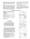
Jnstamling Nandme
INSTRUCTIONS
BENT
TABS SAD_
FIG. 1
OF SADDLE
OPEN END
OF HANDLE
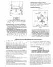
TNE WREELS AND HANDLE DO NOT PRO,
VDE ADEQUATE CLEARANCE STAB_UTY
OR SUPPORT FOR PULUNG TRE UNiT UP
AND DOWN STAIRS OR STEPS= TRE UNIT
MUST B£ L_ETED OR PUSNED UP A RAMP°
DO NOT UPT TNE UNiT BY THE _IAN_FOLD
ASSEMBL'£ THE UNiT CAN BE DAMAGED
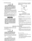
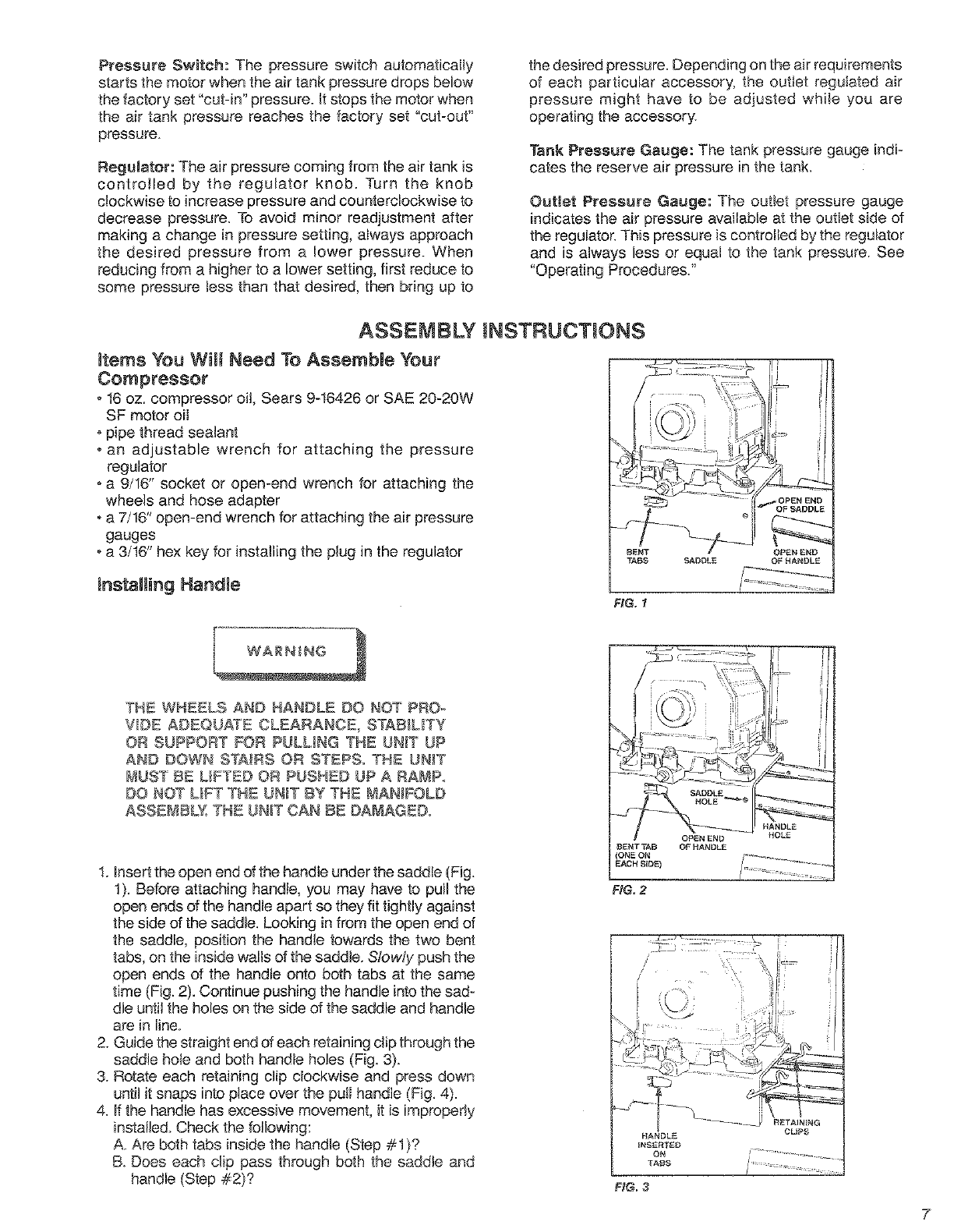
1. Insert the open end of the handle under the saddle (Fig.
t). Before attaching handle, you may have to pull the
open ends of the handle apart so they fit tightly against
the side of the saddle. Looking in from the open end of
the saddle, position the handle towards the two bent
tabs, on the inside waits of the saddle. S!owly push the
open ends of the handle onto both tabs at the same
time (Fig. 2). Continue pushing the handle into the sad-
dle until the holes on the side of the saddle and handle
are in line.
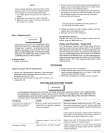
2. Guide the straight end of each retaining clip through the
saddle hole and both handle holes (Fig. 3).
3. Rotate each retaining clip clockwise and press down
until it snaps into place over the putI handle (Fig. 4).
4. If the handle has excessive movement, it is improperly
installed. Check the following:
A. Are both tabs inside the handle (Step #1)?
B. Does each clip pass through both the saddle and
handle (Step #2)?
OPEN END
BENT TAB OF HANDLE
(ONE ON
EACH SEDE)
FHG.2
FgG. 3
7