


-10-
Router Table for the Craftsman
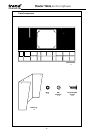
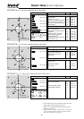
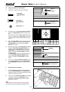
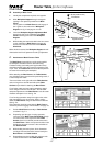
Nylock Nut with
Nylon ring facing down
Insert plate
retaining bolt
Insert plate
adjustment bolt
Nylock Nut
with
Nylon ring
facing up
Fig. G.1
H.
Fitting Insert Plate to Table Surface
1.
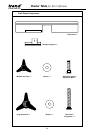
Identify the components required, see below.
2.
Assemble the four Insert Plate Adjustment Bolts
and the four Nylock Nuts to table as shown in fig.
G1.
After a few turns some resistance will be felt as the
screws are gripped by the Nylock Nuts. Screw just
enough to leave a few threads protruding through
the nut.
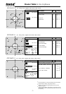
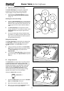
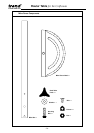
3.
Place the Insert Plate into the large opening in the
table. The position of the plate should be with the
Threaded Hole to the front right of the Table
Surface, see fig. G2.
4.
While pressing down on the Insert plate, gradually
adjust the Insert Plate Adjustable Bolts with a
screwdriver until the Insert Plate is level with the
Table Surface. A steel rule or T-square can be
placed on the top of the Insert Plate to help this
levelling process.
The Insert Plate must be be supported equally on
all four Insert Plate Adjustment Bolts. When
pressure is applied, the Insert Plate should be
stable.
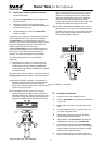
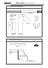
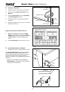
5.
Insert the four Insert Plate Retaining Bolts and fit
the four Nylock Nuts to secure the Insert Plate to
the Table Surface, and tighten securely, see fig.
G.3.
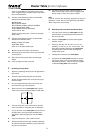
Insert Plate
Adjustable Bolts
x 4
Nylock Nuts x 8
Insert Plate
Retaining Bolts
x 4
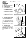
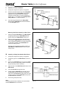
I.
Fitting Router to Insert Plate
1.
Turn the table onto its side, invert the router and
line up the Mounting Holes in the Insert Plate, as
identified in section D, with the appropriate securing
points in the base of the router.
2.
Insert the correct Router Fixing Bolts, as identified
in section D, through the Insert Plate and into
router base. Fit appropriate washers and nuts if
applicable, see fig. H.
Note
Some models of router will require removal of plastic
base prior to fitting, see Section D and pages 6 and 7.
Threaded hole for Lead-on Pin
Fig. G.2
Fig. G.3
Fig. H