


-2-
Router Table for the Craftsman
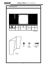
INTRODUCTION
This Router Table is designed for the woodworking
Craftsman and especially those new to the art of routing.
The Router Table has the necessary features to extend
the versatility of most portable routers when profiling,
edging, rebating and jointing.
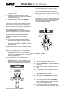
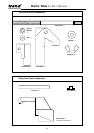
The table includes the following features:
●
A large machined aluminium Table Surface
●
A Back Fence with Workpiece Support and Dust
Extraction Point
●
A clear Retractable Safety Dust Guard
●
An adjustable sliding Mitre Fence
●
A sliding Push Block for producing tenons
●
A pre-drilled Insert Plate to fit most popular routers
●
Insert Rings to reduce the 2 1/8" (54mm) cutter
aperture
●
A Lead-on pin for safer profiling with bearing
guided cutters without a Back Fence
●
No-Volt Release Switch - 230 volts
●
Plastic Pushstick
The following Optional Extras are also available
through your Trend stockist:
●
Spring Pressure Clamps
●
Safety Profiling Top Guard
●
Extraction Hose and Adaptor
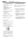
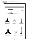
TOOLS REQUIRED FOR ASSEMBLY OF TABLE
A set of spanners and a screwdriver are required for the
initial assembly of the table. Additional screws or nuts/
bolts will be required for mounting the table to a suitable
surface.
Spanners 8mm, 10mm
and 11mm
Screwdriver with flat head
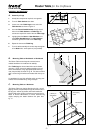
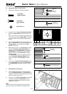
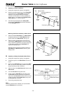
MOUNTING OF ROUTERS
Most popular makes of router can be mounted to the
table, providing the correct model of table is purchased.
Additional modification may be required for certain
models of router and are described in sections E to
G. Additional tools may be required to make these
modifications.
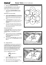
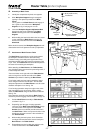
Choice of router will depend on shank size of cutters that
will be used. Higher powered routers will be required for
using larger diameter cutters or for making heavier cuts.
Additional plates can be purchased if more than one type
of router is to be mounted to the table.
CONTENTS ________________________ Page
Contents, Introduction, Tools Required _______ 1
Safety Precautions, Specs, Cutter Care, Advice 3
Assembly Instructions
A.
Assembly of Legs ________________________ 5
B.
Mounting Table to Workbench or Workboard___ 5
C.
Mounting Table to a Workmate _____________ 5
D.
Identification of Mounting Holes and Screws ___ 8
E.
Re-Drilling of Router Base _________________ 8
F.
Re-Drilling of Insert Plate __________________ 9
G.
Re-Drilling of Insert Plate and Router base ____ 9
H.
Fitting Insert Plate to Table Surface _________ 10
I.
Fitting Router to Insert Plate_______________ 10
J.
Selecting & Fitting Insert Plate Rings ________ 11
K.
Fitting Lead-on Pin ______________________ 11
L.
Assembly & Mounting of Tenon Push Block __ 13
M.
Assembly of Safety Dust Guard to Back Fence 13
N.
Assembly of Back Fence _________________ 15
P.
Attachment of Back Fence to Table _________ 15
Q.
Assembly & Alignment of Mitre Fence _______ 17
R.
Fitting of No-Volt Release Switch ___________ 17
Optional Accessories
S.
Dust Extraction Equipment ________________ 18
T.
Assembly of Spring Pressure Clamp ________ 19
U.
Assembly of Profiling Top Guard ___________ 20
Operation
V.
Edging & Profiling using the Back Fence _____ 21
W.
Using Router Table for Grooving ___________ 22
X.
Using Mitre Fence ______________________ 22
Y.
Using the Profiling Top Guard _____________ 24
Z.
End Cutting with the Tenon Push Block ______ 26
Spare Parts Diagram ____________________ 28
Appendix
Plan for base of Hitachi TR12 _________________ 30
Plan for base of Ryobi R600, RE600 ___________ 31
Plan for base of Skil 1835U, 1875U1 ___________ 32
Plan for base of Elu MOF96(E) Mk1
and other similar makes _____________________ 33
Plan for the Elu OF97(E) gasket _______________ 34
Plan for the Bosch POF52, 400A, 500A
& 600 ACE gasket__________________________ 35