


CAP-215
v
Instruction Manual Oil-Less Compressors
REMOTE INLET FILTERS
Depending on the size of the compressor and the size and
construction of the room in which the unit operates, the air inlet
may have to be located outside of the room. If it is necessary
to remotely install the air filter, make the inlet piping as short
and direct as possible. Remotely installed air filters can lead to
vibrations in the inlet piping. These vibrations can be
minimized by adding a pulsation dampener in the inlet piping
between the remote inlet filter(s) and the compressor.
If the Intake is piped to outside atmosphere, a hooded filter
should be installed to prevent water or snow from being
ingested into the compressor.
All inlet piping should be at least the same size (or larger) in
diameter as the inlet connection to the compressor. For every
10 feet of inlet piping or every 900 bend, increase the inlet
piping diameter by one pipe size. The inlet piping must be
thoroughly clean inside. Remove all weld slag, rust or dirt.
Galvanized pipe with threaded or flanged fittings is preferred.
CAUTION!
Never locate the compressor air inlet system where toxic,
volatile or corrosive vapors, air temperatures exceeding
104°F., water, or extremely dirty air could be ingested. These
types of atmospheres could adversely affect the performance
of the compressor system.
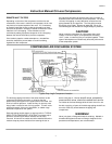
COMPRESSED AIR DISCHARGE SYSTEM
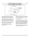
Typical Drop Leg & Component Location
The discharge piping should be of the same diameter as the
compressor discharge connection, or sized so that the
pressure drop at any point in the system does not exceed 10%
of the air receiver pressure. Install auxiliary air receivers near
heavy loads or at the far end of a Iong system. This will insure
sufficient pressure if the use is intermittent, or sudden large
demands are placed on the system.
Discharge piping should slope to a drop leg (refer to TYPICAL
DROP LEG & COMPONENT LOCATION) or moisture trap to
provide a collection point where moisture can be easily
removed. All service line outlets should be installed above the
moisture traps to prevent moisture from entering the tool or
device using the air. Manual
shutoff valves, protected by
pressure relief valves, should be installed at all service
line outlets to eliminate leakage while the tools are not in use.
As with any piping, all parts of the discharge piping should fit so
as not to create any stress between the piping and
components.
WARNING!
Never join pipes or fittings with lead-tin soldering. Welded or
threaded steel pipes and cast iron fittings, designed for the
pressures and temperatures, are recommended.