


vi
CAP-215
Instruction Manual Oil-Less Compressors
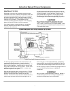
SYSTEM COMPONENTS
Efficiency and safety are the primary concerns when selecting
components for compressed air systems. Products of inferior
quality can not only hinder performance of the unit, but could
cause system failures that result in bodily harm or even death.
Select only top quality components for your system. Call your
local Curtis-Toledo Distributor for quality parts and professional
advise.
DRIVE PULLEYS
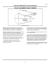
Drive pulleys must be properly aligned and drive belt tension
set to specifications (refer to PULLEY ALIGNMENT & BELT
TENSION). Improper pulley alignment and belt tension can
cause motor overloading, excessive vibration, and premature
belt and/or bearing failure.
DANGER!
Excessive compressor RPM's (speed) could cause a pulley to
burst. In an Instant, the pulley could separate Into fragments
capable of penetrating the belt guard and causing bodily harm
or death. Do not operate the compressor above the
recommended RPM.
GUARDS
All mechanical action or motion is hazardous in varying
degrees and needs to be guarded. Guards should be designed
to achieve the required degree of protection and still allow full
air flow from the compressor sheave across the unit. Guards
shall be in compliance with OSHA safety and health standards
29 CFR 1910.219 in OSHA manual 2206 and any state or local
codes.
WARNING!
Guards must be fastened in place before starting the
compressor and never removed before cutting off and locking
out the main power supply.
CHECK VALVES
Check valves are designed to prevent back-flow of air pressure
in the compressed air system (air flows freely in one direction
only). The check valve must be properly sized for air flow and
temperature. Do not rely upon a check valve to isolate a
compressor from a pressurized tank or compressed air delivery
system during maintenance procedures!
MANUAL SHUTOFF VALVES
Manual shutoff valves block the flow of air pressure in either
direction. This type of valve can be used to isolate a
compressor from pressurized system, provided the system is
equipped with a pressure relief valve capable of being
manually released. The pressure relief valve should be
installed between the manual shutoff valve and the
compressor.
PRESSURE RELIEF VALVES
Pressure relief valves aid in preventing system failures by
relieving system pressure when compressed air reaches a
determined level. They are available in various pressure
settings to accommodate a range of applications. A check
valve and pressure relief valve are required in all compressor
discharge lines. Pressure relief valves are preset by the
manufacturer and under no circumstances should the setting
be changed by anyone other than the manufacturer.
DANGER!
Pressure relief valves are designed to protect compressed air
systems in accordance with ASME B19 safety standards.
Failure to provide properly sized pressure relief valves may
cause property damage, severe personal injury or even death.
PRESSURE SWITCH
The pressure switch detects the demand for compressed air
and allows the motor to start. When the demand is satisfied,
the unit stops. Pressure switches provided by Curtis-Toledo
are pre-set at the factory and usually do not require
adjustment. However, it adjustment is required (by qualified
electrician) refer to instructions inside cover of switch housing,
WARNING!
The maximum discharge pressure for the various models
are established by the Curtis performance data. Do not
set the pressure switch or regulators to exceed the design
limit.
WARNING!
Electric power always exists Inside the pressure switch
whenever the compressor package is connected to a
power supply. Be careful not to touch any electrical leads
when setting the pressure switch.