


8
CAP-215
Instruction Manual Oil-Less Compressors
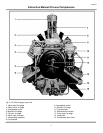
1.2. DESIGN AND MODE OF OPERATION
1.2.1 DESIGN
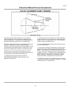
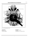
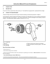
The design of the oil-less compressor is
shown in Fig. 1 to Fig. 4. For drawings
refer to the annex of this manual.
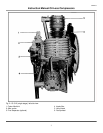
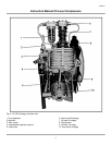
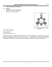
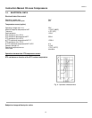
Fig. 7: Position of stages at 2-stage
compressor
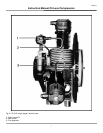
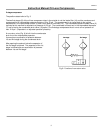
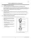
1.2.2. Mode of Operation
1-stage compressor
The positions stated refer to Fig. 1.
The outside air is drawn in through the three first stages (3) of the oil-less compressor via intake filter, crankcase and
piston and compressed to a final pressure of max. 110 psi
a)
. The compressed air is cooled back to the original
temperature in the after-coolers (2) and is then lead to a manifold (1). After that it reaches the final separator (6), where
the condensate is filtered out. The condensate is drained regularly by the automatic condensate drain (8)(option)