


PeakStopPlus
®
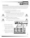
Switch and LED: The dynamics of the dbx 162SL are set to handle fast transients
through PeakStop
®
limiting and the newer PeakStopPlus. PeakStop is the process first introduced on
the dbx 165A compressor/limiter. PeakStop is made up of an extremely fast-reacting detector, called
Instantaneous Transient Clamp. The sound of PeakStop became popular as the 165A permeated the
audio industry, and quickly became the standard looked for by many top artists of the day. The lat-
est implementation of this limiter topology is PeakStopPlus, first introduced in 1996 on the dbx 1066.
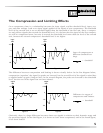
PeakStopPlus is made up of two different parts or stages. The first stage is the Instantaneous
Transient Clamp™ which clamps the signal with a soft logarithmic clamp function. This logarithmic
function assures that the signal will not exceed the level set by the PeakStopPlus Level control by
more than 2 dB typically, and that it will not introduce harsh artifacts. The second stage is a unique
program limiter featuring Intelligent Predictive Limiting™. Its function is to monitor the input signal
and intelligently predict the amount of gain reduction needed to keep the output signal below the
ceiling set by the Instantaneous Transient Clamp™.
Note that since the PeakStopPlus limiter is a fail-safe limiter it must come after the Output Gain con-
trol. If the output gain is set too high as compared to the PeakStopPlus LEVEL control, continuous
limiting can occur. While PeakStopPlus is typically used as a protective function, creative effects can
be achieved by intentionally driving the signal into heavy PeakStopPlus limiting. Great care has gone
into the design of the PeakStopPlus limiter to keep it acoustically transparent. Appropriate use of it
can protect your gear while keeping the signal free of artifacts.
A bi-color LED associated with both the Stop Level control and the PeakStopPlus switch indicates
when PeakStopPlus is activated. By pushing the PeakStopPlus switch to the IN position, the LED
lights in a green color when the signal level at the limiter circuit is BELOW the stop level set by the
Stop Level control. When the signal level attempts to exceed the level set by the Stop Level con-
trol, the LED lights in a red color.
When the limiter is in P
EAK
S
TOP
mode, the LED does not light in a green color, and only lights in a
red color when the signal attempts to exceed the set stop level, showing that the signal is being
reduced in level by the limiter.
Sidechain Switch and LED: This switch/LED provides access/visual feedback to the sidechain con-
trol. When the switch is IN, the LED is lit, and the 162SL is operating in sidechain mode. This means
that the compressor is set react to the audio signal presented at the Sidechain Return connector,
rather than to the audio signal presented at the regular audio input of the 162SL. The circuitry of the
162SL was designed in such a way as to make the audio path of the sidechain section very short and
clean. The selection of the sidechain function is made via “relay” switching, not allowing the signal
to pass through any unnecessary switches. The sidechain functions are convenient in many applica-
tions, such as broadcast engineering, where engineers are asked to provide “ducking” functions, as
well as de-essing. Frequency-specific and sustain-related compression are also possible with the use
of the sidechain functions of the 162SL. See the section entitled Operating Notes.
12