


Note that the gain reduction scale is linear in dB as opposed to the standard VU markings on the
upper scale on which input and output levels are monitored. This allows for easy visual indication
of gain reduction, as it can be read in a fraction of a second, with only a fleeting glance from the
engineer.
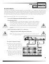
Input Meter Selection Switch and LED:Selecting this mode via the switch allows the user to
monitor the incoming signal on the logarithmic (upper) scale of the VU meter. When in input mode,
the LED above the switch will light in a green color, indicating that input mode is selected. This works
in conjunction with the input level switch (+4dBu/-10dBV) on the back of the 162SL. When the rear
switch is set to +4dBu, a meter reading of 0VU corresponds to +4dBu input. When the rear switch
is set to -10dBV, a meter reading of 0VU corresponds to -10dBV input.
Output Meter Selection Switch and LED: Selecting this mode via the switch allows the user to mon-
itor the outgoing signal on the logarithmic (upper) scale of the VU meter. When in output mode, the
LED above the switch will light in a yellow color, indicating that output mode is selected. This works
in conjunction with the input level switch (+4dBu/-10dBV) on the back of the 162SL. When the rear
switch is set to +4dBu, a meter reading of 0VU corresponds to +4dBu output. When the rear switch
is set to -10dBV, a meter reading of 0VU corresponds to -10dBV output.
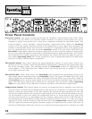
Gain Reduction Meter Selection Switch and LED: Selecting this mode via the switch allows the
user to monitor the amount of gain reduction in dB, applied to the signal on the linear (lower) scale
of the VU meter. When in gain reduction mode, the LED above the switch will light in a red color,
indicating that gain reduction mode is selected. In gain reduction mode the meter displays the
amount of gain reduction resulting from the settings of both the compressor and PeakStopPlus® lim-
iter.
Stereo Couple Switch and LED: This switch activates the stereo linkage between channels one and
two. When the switch is in the IN position, the two channels of the 162SL are linked together, and
the oversized yellow LED directly above the switch lights to indicate the selection. In stereo mode
channel one (the left side of the 162SL) is the “master” and channel two (the right side of the 162SL)
is the “slave”. When the two channels are linked together, the controls on the master side control the
settings of both channels of the 162SL. The controls on the slave side are disabled, although the meter
moves synchronous to the meter on the master side. In stereo mode, the 162SL uses a process called
True RMS Power Summing™. True RMS Power Summing combines the RMS signal energy (power)
of the audio signal of both channels and allows the 162SL to operate based on the signal informa-
tion from both the right an left channels of audio signal.
Power LED: The Power LED is located directly above the Stereo Couple switch, at the center point of
the 162SL. It remains lit while the 162SL is connected to an appropriate power supply, and the Power
switch is in the ON position.
14