


15
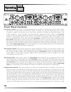
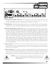
Audio Input and Output Connectors: Each audio input and output channel of the 162SL offers both
1/4” and XLR connectors. The connectors are default wired in balanced mode (pin 2 /tip hot),
although supplying an unbalanced signal presents no difficulty to the 162SL.
Pin 1 Lift Switch: Associated with each input connector is a switch labeled Pin 1 Lift. Depressing this
switch lifts pin 1 of the input XLR and the sleeve of the 1/4” connector from all ground references.
This may be necessary to break a troublesome ground loop which is causing hum in the system.
Sidechain Send and Return Connectors: When the front panel Sidechain switch is in the IN posi-
tion, the 162SL RMS level detection is “listening” to the audio signal presented at the Sidechain Return
connector. Each channel features separate sidechain capabilities using the 1/4” TRS connectors as for
the main audio input and output connections. Each channel’s sidechain connections are marked
“send” for the output, and “return” for the input. When selected, the sidechain Send connector
“sends” the audio signal from the 162SL to the outboard gear in the sidechain loop. (ie: dbx 20 or
30 Series Graphic Equalizer or digital delay. See the section marked Operating Notes for more infor-
mation on the sidechain functions of the 162SL.) The audio is processed, and sent from the output
of that device back to the 162SL via the Return connector. As the signal is brought back into the
162SL, its RMS level is used to trigger the compression/limiting. This allows the 162SL to be very ver-
satile in many applications, from ducking to frequency-specific compression or limiting. Two sepa-
rate cables are used in favor of the conventional single “Y” cable, because they supply balanced sig-
nal to the sidechain gear, and are much more convenient to locate and use in a fast-paced studio or
live sound environment.
AC Power Switch:
Located above the AC Power connector, the AC Power switch turns the 162SL ON
and OFF. When the switch reveals the red portion of the switch, the AC power to the 162SL is ON.
When the switch is in the opposite position, no AC power is being supplied to the 162SL, regardless
of other power connections.
AC Power Connector: The AC Power connector is a standard IEC 320 power inlet receptacle, for use
with any IEC-type power cord (included with the 162SL). Connect this cable to any 50Hz or 60Hz AC
power source of the correct line voltage for your area. Make sure this voltage is also correct for the
voltage marked on the back of the 162SL. Always make AC power connections with the AC power
switch in the OFF position (see above). The 162SL consumes a maximum power of 28 watts.
Warning:
Be sure to verify both your actual line voltage and the voltage for which your
162SL is wired, as indicated on the back panel of the unit. Connection to an
inappropriate power source may result in extensive damage which is not cov-
ered by the warranty.
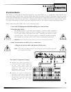
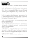
Rear Panel
28 WATTS
POWER
RETURN SEND
GND
LIFT-10 dBV
+4 dBu
SIDECHAIN
OUTPUTS
INTPUTS
CHANNEL 2
RETURN SEND
GND
LIFT-10 dBV
+4 dBu
SIDECHAIN
OUTPUTS
INTPUTS
CHANNEL 1
100V-120V T 400mA L 250V
T 200mA L 250V
FUSE REPLACEMENT RATINGS
220V-240V
PHONE:
TIP
RING
SLEEVE
XLR:
PIN 1
PIN 2
PIN 3