


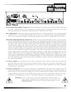


Bypass Switch and LED: This switch activates a hard-wire relay bypass system, which allows the
audio signal to pass through the compressor directly from input to output, even when the 162SL is
turned off. That is to say that the XLR Pin 2 at the input connector is directly connected to the XLR
Pin 2 at the output connector, and the XLR Pin 3 at the input connector is directly connected to the
XLR Pin 3 at the output connector. When the 162SL is in bypass mode the LED directly above the
Bypass switch is lit.
Note: Bypass mode can be very useful for applications such as A-B comparisons, comparing processed signal
with un-processed signal.
Output Gain Control: This control adjusts the amount of gain in the 162SL’s output amplifier stage.
The signal can be attenuated or boosted by a full 20dB relative to a “0” center setting, representing
unity gain. This control is independent of the threshold or compression ratio settings. Because 20dB
of gain can be added at the 162SL output, it is possible to cause clipping even when the input level
is within the specified range. When the compression ratio is set at a low number, extreme clockwise
rotation of the Output Gain control could cause the 162SL output stage to clip audio program peaks.
Therefore, for normal operation we suggest setting the Output Gain control to “0dB” (12 o’clock posi-
tion) as a starting position. Where the circuit fed by the 162SL has a high input sensitivity, lowering
the output gain setting can avoid the need for an attenuation pad in subsequent equipment.
Peak LED: This LED is located to the left of the VU Meter. It is set to light when the signal level at the
output level reaches +21dBu. This represents a headroom measurement of approximately 3dB before
hard clipping will occur, due to the maximum output level of the 162SL (+24dBu).
VU Meter: The custom designed analog meter is made to serve 3 different functions: first, it measures
the amount of input signal presented at the input connector corresponding to its channel. Second, it
measures the output signal at the output connector, after all processing has taken place, including
output gain. Third, it shows the amount of gain reduction being induced into the input signal, mea-
sured after both the compressor settings and limiter settings. Note that the meter, in input and out-
put mode, measures accurately from -30dB to +6dB. There is 15dB between the upper end of the
meter, and the setting at which the Peak LED lights. Be aware that while the occasional “pegging” of
the meter will likely not effect the internal dynamics of the 162SL, it is possible that the output sig-
nal from the 162SL could cause distortion in subsequent gear, if the output signal stays above the
+6dB marking on the meter for an extended period of time. The dynamic range of the 162SL is meant
to provide an extremely low noise floor at optimum operating level (“0”dB, which is +4dBu), and to
provide protection for the occasional excursion above the nominal operating range. It was not meant
to provide continuous operation in the 15dB of “no-man’s-land” between the upper end of the ana-
log meter and the setting of the Peak LED.
In Gain Reduction mode, the meter moves to indicate the amount of gain reduction, in dB, the com-
pressor/limiter settings are imposing on the output signal. When first activated, the meter’s needle
will jump to the “0” mark of the lower scale on the meter (only if there is no gain reduction hap-
pening), indicating “zero gain reduction”, and will move to the left indicating the amount of gain
reduction in the signal level, up to a maximum of 30dB of gain reduction.
13