


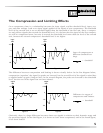


The Compression and Limiting Effects
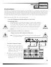
On a compressor, there is a relationship between the input signal, and the threshold level, input, out-
put, and ratio settings. Look at an input signal applied to the inputs of two compressors. The threshold
level of the second unit is set ten decibels higher than the threshold of the first unit. Since a compres-
sor only affects signals that exceed the threshold level, it is obvious that the signal of the first compres-
sor will be compressed more, because it exceeds the threshold level more than the level of the second
unit, because the second compressor’s threshold level is set higher.
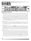
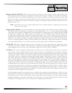
The difference between compression and limiting is shown visually below. In the first diagram below,
compression “squashes” the signal. Its peaks are lowered, but the overall level of the signal is raised due
to applied make-up gain (Output Gain). In the second diagram, the peaks are lowered to the threshold
level, but the rest of the signal has not been altered.
Obviously, there is a large difference between these two signals in relation to their dynamic range and
the processed signal. In the third figure, it is shown to have been compressed, and in the fourth figure,
it has been limited.
5
+10
0
-10
-20
time
Figure 1
input
dBu
+10
0
-10
-20
time
+10
0
-10
-20
time
input
dBu
Figure 2 Figure 1
input
dBu
Input of compressors at
different threshold set-
tings.
= threshold
Figure 3 Figure 4
+10
0
-10
-20
time
+10
0
-10
-20
time
output
dBu
output
dBu
Difference in output of
compressors and limiters.
= threshold