


11
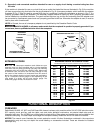
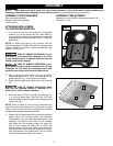
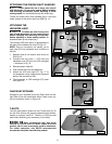
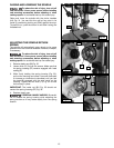
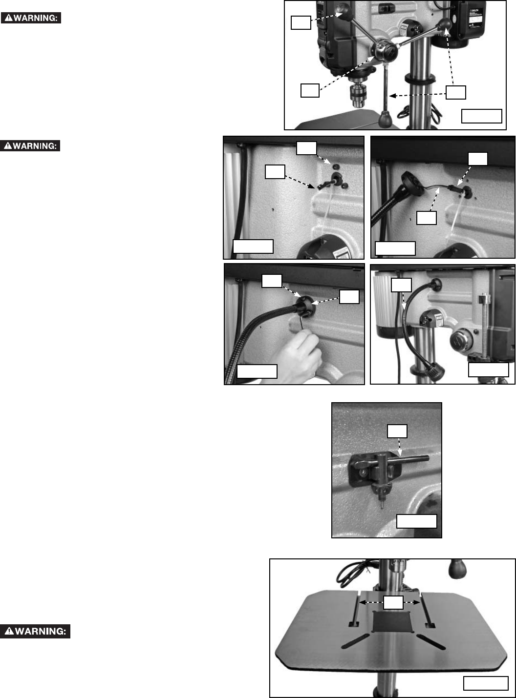
ATTACHING THE PINION SHAFT HANDLES
To reduce the risk of injury, turn unit off
and disconnect it from power source before installing
and removing accessories, before adjusting or when
making repairs. An accidental start-up can cause injury.
Thread the three pinion shaft handles (AA) in the three
holes located in the pinion shaft hub (BB) Fig. 14.
ATTACHING THE
LED WORK LIGHT
To reduce the risk of injury, turn
unit off and disconnect it from power source
before installing and removing accessories,
before adjusting or when making repairs. An
accidental start-up can cause injury.
The included LED work light is to be attached to
the side of the headstock at wire (CC) Fig. 15.
NOTE: Prior to connection, be careful not to
push wire (CC) into headstock as it is difficult to
retrieve.
1. Remove three 6 mm screws (one shown at
DD) Fig. 15.
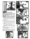
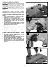
2. Connect the two wires — (CC) from the
headstock and (EE) from the LED worklight
— as shown in Fig. 16.
3. Remove plastic cable tie.
4. Push excess wire into the headstock.
5. Attach the LED work light (FF) Fig. 17 to
the headstock using three screws removed
earlier. One is shown at (DD).
6. Final assembly of LED worklight (FF) looks
like Figure 18.
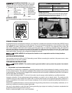
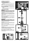
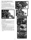
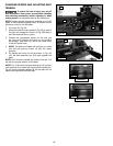
CHUCK KEY STORAGE
Storage for your included chuck key (GG) is built into the
right side of the drill press head stock. Press chuck key
into the holder as shown in Figure 19.
Fig. 19
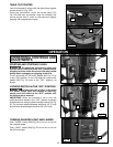
T-SLOTS
The drill press table is fitted with two T-slots (HH) Fig. 20
for use with various drill press accessories (stop blocks,
fences, or clamps). Use 5/16" T-bolts or 1/4-20 hex head
bolts when attaching your accessory to the table.
Since accessories other than those
offered by DELTA have not been tested with this
product, use of such accessories could be hazardous.
For safest operation, only DELTA recommended
accessories should be used with this product.
HH
Fig. 20
FF
DD
AA
AA
Fig. 14
Fig. 15
CC
CC
Fig. 16
Fig. 17
EE
Fig. 18
FF
GG
BB
DD