


8
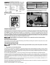
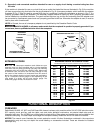
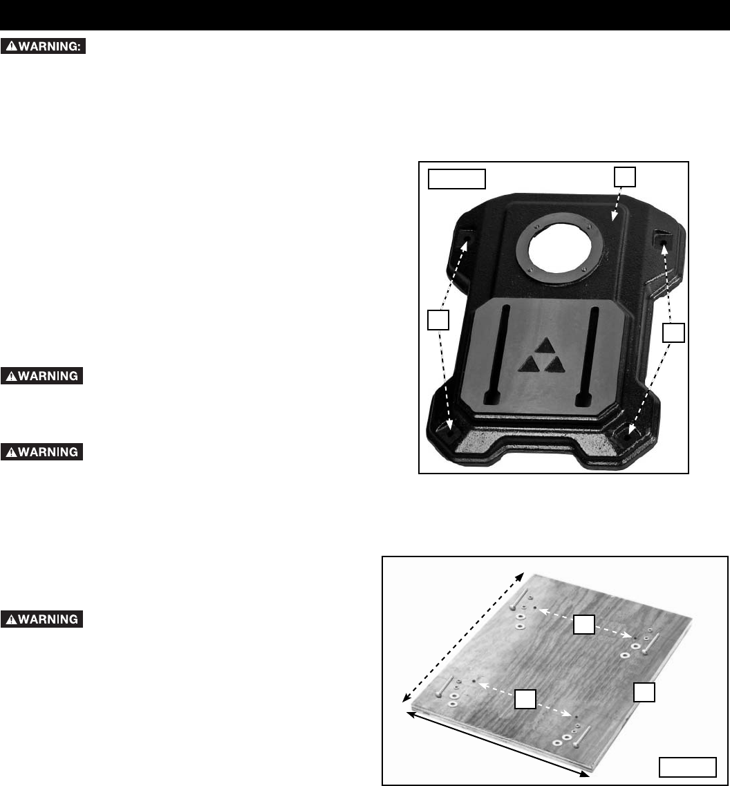
29" (737 mm) MINIMUM
24" (610 mm) MINIMUM
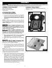
ATTACHING DRILL PRESS
TO SUPPORTING SURFACE
1. If you plan to use your drill press in a permanent
location, you must secure the drill press base to
the supporting surface with fasteners (not supplied)
through the four mounting holes (A) Fig. 1 in the drill
press base.
NOTE: To attach the base to the plywood, use the
following hardware: (4) M8x1.25x125 mm carriage head
screws, (8) M8 flat washers, (4) M8 lockwashers, and
(4) M8x1.25 hex nuts.
RISK OF UNSAFE OPERATION. If your
drill press is not permanently fastened to the floor
it may be mounted to a plywood board to improve
stability and prevent tipping.
RISK OF UNSAFE OPERATION. Use a
good grade of plywood with a minimum 3/4" (19 mm)
thickness. Do not make the mounting board from
particle board since particle board breaks easily.
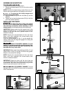
2. Use a plywood board base with the minimum
dimensions as shown in Fig. 2 for mounting the drill
press base (B) Fig. 1 to a supporting surface.
3. Place the drill press base centered on the plywood
(D).
RISK OF UNSAFE OPERATION. Make
sure that the plywood extends a minimum of 3"
(76.2 mm) on all four sides of the base.
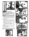
4. Mark four holes (C) Fig. 2 through the holes (A) Fig.
1 in the drill press base. Then drill 3/8" (9.5 mm)
diameter holes at these locations into the supporting
surface (D) Fig. 2.
NOTE: Place a piece of scrap wood underneath the
supporting plywood surface when drilling the through
holes so that the drill bit will not damage the material
beneath the plywood supporting surface.
5. Fasten the drill press base to the mounting plywood
board using the carriage bolts, flat washers,
lockwashers, and hex nuts described above (not
supplied). Countersink the holes for the carriage
bolt heads and flat washers under the board so
that the bolt heads are flush with or below the
bottom surface of the board after you insert them
up through the holes below the supporting surface.
Use a flat washer, lock washer and hex nut above
the drill press base to fasten the screws.
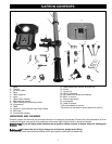
ASSEMBLY TOOLS REQUIRED
Hex wrenches (supplied)
Rubber mallet (not supplied)
10mm wrench
Fig. 2
C
ASSEMBLY
To reduce the risk of injury, turn unit off and disconnect it from power source before installing and
removing accessories, before adjusting or when making repairs. An accidental start-up can cause injury.
ASSEMBLY TIME ESTIMATE
Assembly for this machine takes approximately 30
minutes to 1 hour.
C
D
Fig. 1
A
A
B