


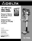

9
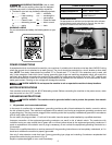
ASSEMBLING DRILL PRESS PARTS
RISK OF UNSAFE OPERATION. If your
drill press is not permanently fastened to the floor
it may be mounted to a plywood board to improve
stability and prevent tipping.
To reduce the risk of injury, turn unit off
and disconnect it from power source before installing
and removing accessories, before adjusting or when
making repairs. An accidental start-up can cause injury.
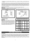
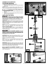
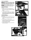
1. Attach the column (E) Fig. 3 to the base (B) using the
four M10 x 40 mm socket head cap screws (F), three
of which are shown.
NOTE: Make sure screw (G) (Fig. 3 inset) is oriented to the
back of the drill press.
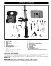
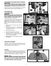
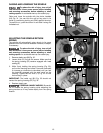
2. Attach the table raising and lowering handle (H) Fig. 4
to the worm gear shaft (I). Tighten the set screw (J)
against the flat on the shaft with the 3 mm hex wrench
supplied.
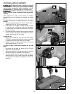
3. Thread the table clamp handle (K) Fig. 5 in the hole (L)
in rear of table bracket and secure tightly.
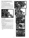
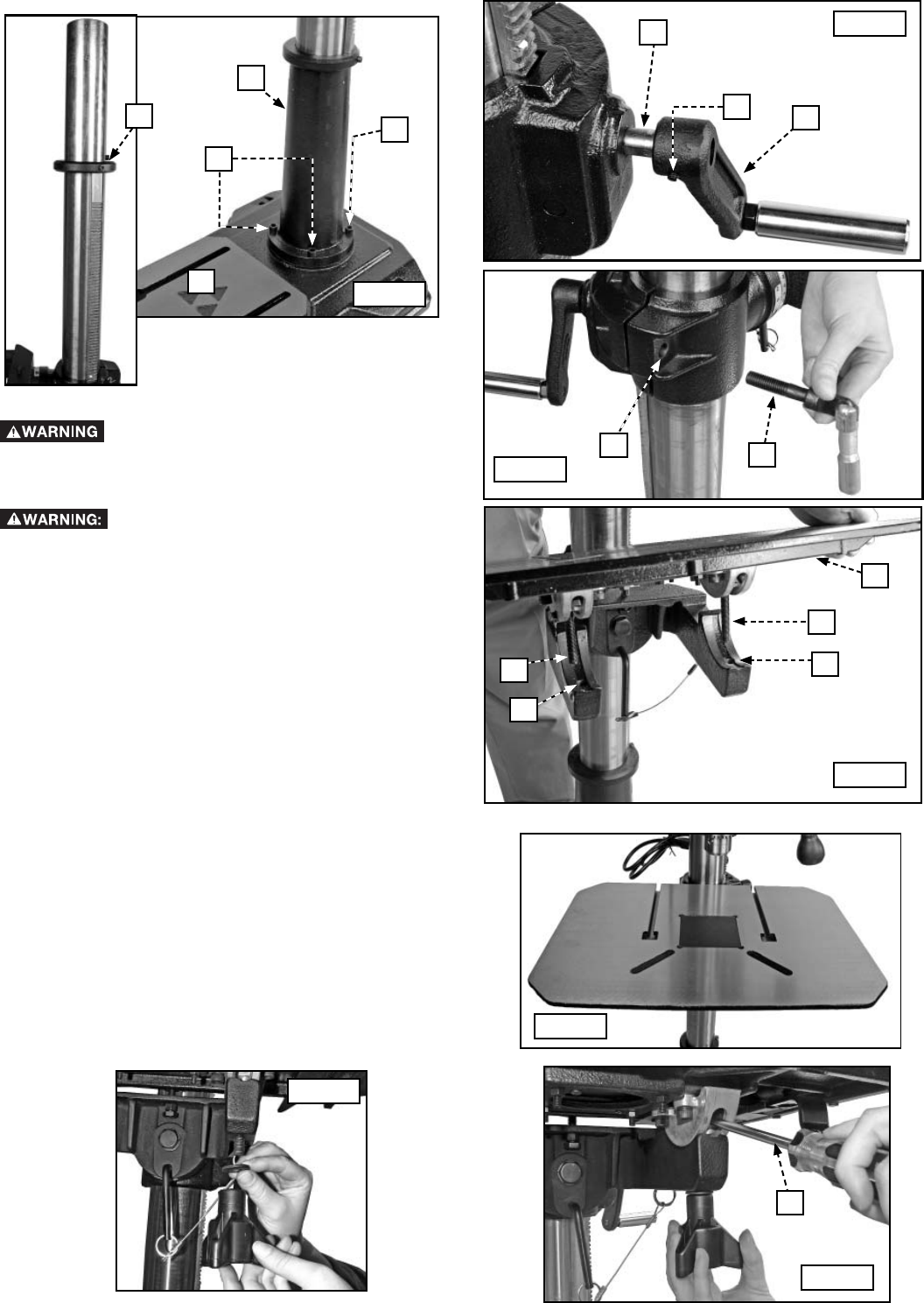
4. Align the bolts (M) Fig. 6 on the table (Q) with the holes
in the table support (N) and set the table on the table
supports.
NOTE: Be sure to properly orient your drill press table to the
column as shown in Fig. 6A.
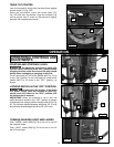
5. Install the washers and forward tilt knobs as shown in
Fig. 7. Tighten securely.
NOTE: The bolts in the trunnion are moveable. To install
knobs more easily, insert a fl athead screwdriver (O) Fig. 8
in the opening of the trunnion against the bolts to steady
them.
Fig. 3
Fig. 4
F
B
F
H
I
J
G
E
Fig. 5
K
L
M
M
N
N
Fig. 6
Fig. 6A
Q
Fig. 7
Fig. 8
O