


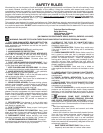


Fig. 17
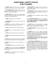
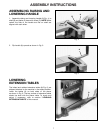
Fig. 18
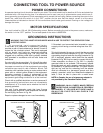
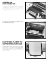
Fig. 19
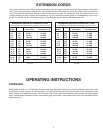
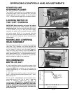
Fig. 20
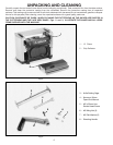
LEVELING
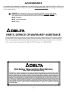
EXTENSION TABLES
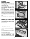
For optimum performance, the extension tables, one of
which is shown at (A) Fig. 17, must be level with the
planer table. To check the extension tables and adjust if
necessary, proceed as follows:
1. Place a straight edge (B) Fig. 17, on the infeed ex-
tension table (A) with one end extending out over the
extension table as shown. Check to see if the infeed
table is level with the planer table on both ends of the
extension table.
2. If an adjustment is necessary, loosen locknut (C)
Fig. 17, and adjust stop screw (D) on each side of the
extension table (A) until the extension table is level with
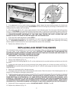
the planer table (E); then tighten locknut (C). Recheck
and make certain inside edge of table extension is
perfectly level with the planer table. If necessary, loosen
two screws (F), adjust extension table and retighten two
screws (F). Adjust opposite side of the table in the same
manner. Make certain the extension table is solidly
supported when there is downward pressure on the
table.
3. Check and adjust outfeed extension table in the
same manner.
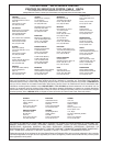
STORING THE POWER CORD
Wire hangers (A) Fig. 18, are provided on the underside
of the outfeed extension table as shown, to store the
power cord (B) when the planer is not in use and when
transporting the machine.
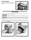
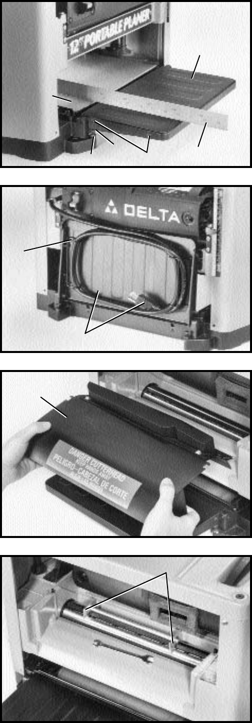
ADJUSTING KNIVES
To check and adjust the knives, proceed as follows:
1. DISCONNECT THE TOOL FROM THE POWER
SOURCE.
2. Lower the head assembly by turning handle (B) Fig.
15.
3. Remove chip deflector (A) Fig. 19.
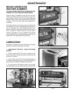
4. Carefully place knife setting gage (B) Fig. 20, on the
cutterhead so the rounded sections are directly over the
knife as shown. When adjusted correctly, the knife
should just contact the bottom of the center portion at
each end of gage (B). Check the other knife in the same
manner.
A
B
E
C
D
F
A
B
A
B
10