


11
5. If an adjustment to one or both knives is necessary, slightly loosen the seven locking screws, six of which are
shown at (C) Fig. 21, by turning the screws CLOCKWISE into the knife locking bar just enough to relieve stress in the
cutterhead and not disturb the knife setting.
6. With setting gage (B) Fig. 20, in place, apply pressure to the knife being reset. Turn the seven knife locking screws
(C) Fig. 21, CLOCKWISE until the knife locking bar becomes loose. Lift springs will automatically raise the knife until
it comes in contact with gage (B) Fig. 20. Snug the knife locking bar by lightly turning the seven locking screws (C) Fig.
21, COUNTERCLOCKWISE. IMPORTANT: AT THIS TIME, ONLY TIGHTEN THE KNIFE LOCKING BAR JUST
ENOUGH TO HOLD THE KNIFE IN POSITON INSIDE THE CUTTERHEAD SLOT.
7. If the other knife needs adjustment, repeat STEP 6.
8. After both knives are positioned in the cutterhead, turn each of the seven screws, six of which are shown at (C)
Fig. 21, COUNTERCLOCKWISE until the knife is secure in the cutterhead. NOTE: When tightening knife locking
screws, tighten the end screws first, then inward toward the center of the cutterhead.
9. Replace chip deflector (A) Fig. 19.
REPLACING AND RESETTING KNIVES
The cutterhead knives supplied with the machine are dual-edged. When one side becomes dull, they can be flipped
over and reset in the cutterhead and used again. CAUTION: IF THE KNIVES ARE TO BE REMOVED FOR
SHARPENING OR REPLACEMENT, EXTREME CARE SHOULD BE TAKEN AS THE KNIVES ARE VERY SHARP. TO
REPLACE OR RESET THE KNIVES, PROCEED AS FOLLOWS:
1. DISCONNECT THE TOOL FROM THE POWER SOURCE.
2. Lower the head assembly by turning handle (B) Fig. 15.
3 Remove chip deflector (A) Fig. 19.
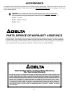
4. Carefully place knife setting gage (B) Fig. 20, on the cutterhead so the rounded sections are directly over the knife
as shown.
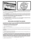
5. Loosen the knife locking bar by turning the seven knife locking screws, six of which are shown at (C) Fig. 21,
CLOCKWISE and carefully remove knife locking bar (D) Fig. 22, knife (E), and springs (not shown) which are located
under the knife.
6. Remove the remaining knife in the same manner.
7. Thoroughly clean the knife slots, knife locking bars and screws. Check the screws. If the threads appear worn or
stripped or if the heads are damaged, replace them.
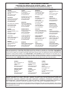
8. Carefully replace the springs (not shown), knives (E) Fig. 22, and knife locking bars (D), into both slots of cutterhead
(F). IMPORTANT: WHEN REPLACING KNIFE LOCKING BARS (D) AGAINST KNIVES (E), AS SHOWN IN THE
CROSS-SECTIONAL ILLUSTRATION Fig. 22, MAKE CERTAIN THE BARS ARE INSTALLED AS SHOWN, WITH
SCREWS (C), POSITIONED AT THE TOP OF KNIFE LOCKING BARS (D), AND ANGLED DOWNWARD HOLDING
THE KNIVES (E) PROPERLY INSIDE THE CUTTERHEAD SLOTS. TURN KNIFE LOCKING SCREWS, ONE OF WHICH
IS SHOWN AT (C), COUNTERCLOCKWISE JUST ENOUGH TO HOLD BOTH KNIVES (E) IN THE CUTTERHEAD (F).
9. Adjust both knives as explained in section “ADJUSTING KNIVES”, STEPS 6, 7 and 8.
10. Replace chip deflector (A) Fig. 19.
Fig. 22Fig. 21
C
C