


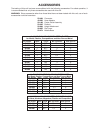


1212
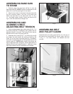
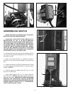
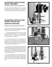
ADJUSTING LOWER BLADE
GUIDES AND BLADE
SUPPORT BEARING
DISCONNECT MACHINE FROM POWER SOURCE.
The lower blade guides and lower blade support bearing
should be adjusted at the same time as the upper guides
and bearing as follows:
1. The lower blade guides (A) Fig. 27, are held in place
by means of the cap screws (C) Fig. 27. Loosen the cap
screws (C) to remove the guides for maintenance. Note:
Lower the chip chute out of the way.
2. The complete lower guide block assembly bracket (B)
Fig. 27 can be moved in or out by loosening the button
head screw (D) Fig. 27. The guides (A) Fig. 27, should
then be adjusted so that the front edge of the guide roller
bearings are just behind the “gullets” of the saw teeth (F)
Fig. 27. Be careful not to pinch the blade.
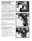
3. Both lower roller bearing assemblies (C) Fig. 28 can
be adjusted by loosening the socket head cap screw (A)
Fig. 28. Slide both bearing assembly guides (D) Fig. 28,
sideways so the roller bearing outer surface is a couple of
thousandths of an inch (about the thickness of a piece of
paper) away from the blade. Tighten securely. Be careful
not to pinch the blade.
4. The rear lower blade support bearing (E) Fig. 27
should also be adjusted so it is a couple of thousandths
away from the back edge of the blade. The lower blade
support bearing, prevents the blade from being pushed
too far to the rear which could damage the set in the saw
teeth.
CHIP CHUTE
The chip chute (B) Fig. 28 can be equipped with acces-
sories for easy connection to a central exhaust system as
shown in (F) Fig. 28 connector and (E) Fig. 28 adapter.
(See ACCESSORIES)
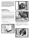
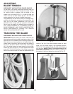
CHANGING THE BLADE
MAKE CERTAIN THE MACHINE IS DISCONNECTED
FROM THE POWER SOURCE.
NOTE: Blades for the 14 band saw are 93
1
/2 in length
1. Open the upper and lower wheel guards.
2. Release tension on the band saw blade.
3. Remove the table adjustment pin and table insert.
4. Slide the saw blade off the wheel and guide it out
through the slot in the table.
5. To install the new saw blade, reverse the above pro-
cedure. NOTE: Blade teeth should be pointing downward
at the front of the table.
Fig. 27
D
B
A
C
F
E
Fig. 28
D
B
A
C
F
E
Fig. 29