


99
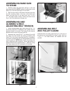
Fig. 17
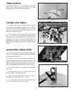
TABLE INSERT
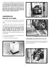
Place table insert (A) Fig. 17, into the hole provided in the
table surface, making certain the pin (B) in the table
engages one of the indents in the table insert.
TILTING THE TABLE
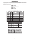
1. The table on the band saw can be tilted 45 degrees
to the right and 10 degrees to the left. To tilt the table to
the right, loosen two locking knobs (A) Fig. 18, tilt the
table to the desired angle as shown on scale (D), and
tighten two locking knobs (A).
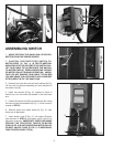
2. To tilt the table to the left, loosen two locking knobs
(A) Fig. 18, and tilt the table slightly to the right until you
can gain access to table stop (B) Fig. 19. Remove table
stop (B) Fig. 19, and tilt the table to the left angle up to
10 degrees and tighten two locking knobs (A) Fig. 18.
NOTE: Readjust the table stop. (See ADJUSTING TABLE
STOP).
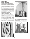
ADJUSTING TABLE STOP
The band saw is equipped with an adjustable table stop
(B) Fig. 19, that allows the table to be set perfectly at
90 degrees with the blade.
Tilt the table to the left until the table stop (B) Fig. 19,
contacts the bottom of the table. Place a square on the
table and against the blade as shown in Fig. 20, and
check to see if the blade is 90 degrees to the table sur-
face. If an adjustment is necessary, proceed as follows:
1. Tilt the table slightly to the right and tighten table
lock knobs.
2. Turn adjustment nut (C) Fig. 19, right or left as nec-
essary to raise or lower table stop (B).
3. Lower the table and make certain the table is
90 degrees to the blade as shown in Fig. 20.
4. It is necessary to remove the adjustable table stop
(B) Fig. 19, when tilting the table to the left.
Fig. 18
A
D
A
Fig. 19
C
B
Fig. 20