


20
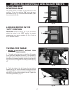
TRACKING THE BLADE
DISCONNECT MACHINE FROM POWER
SOURCE.
BEFORE TRACKING THE BLADE,
MAKE SURE THAT THE BLADE GUIDES AND BLADE
SUPPORT BEARINGS ARE CLEAR OF THE BLADE.
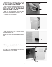
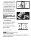
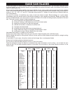
After applying tension to the blade, rotate the upper
wheel slowly forward by hand and observe the blade’s
movement. The blade (A) Fig. 52 should travel in the
center of the upper tire. If the blade creeps toward the
front edge, loosen the wing nut (B) Fig. 51, and turn the
thumb screw (C) clockwise. This action draws the blade
toward the center of the tire. If the blade creeps toward
the back edge, turn the thumb screw in the opposite
direction. Adjust the thumb screw (C) Fig. 51 only a
fraction of a turn each time.
NEVER TRACK THE BLADE WHILE
THE TOOL IS RUNNING.
After the blade is tracking in the center of the tires,
tighten the wing nut (B) Fig. 51.
Fig. 52
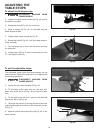
VERTICAL ADJUSTMENT OF
THE UPPER BLADE GUIDE AND
GUARD ASSEMBLY
DISCONNECT MACHINE FROM POWER
SOURCE.
Adjust the blade guides and bearings according to the
following instructions.
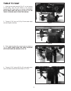
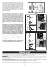
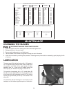
Set the upper blade guide and guard assembly (A) Fig.
53 as close as possible to the top surface of the
workpiece. Loosen the lock knob (B) and move the
guide assembly (A) to the desired position.
Fig. 53
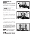
ADJUSTING THE UPPER
BLADE GUIDES AND BLADE
SUPPORT BEARING
Adjust the upper blade guides and blade support
bearings ONLY AFTER the blade has the correct tension
and is tracking properly. To adjust, proceed as follows:
DISCONNECT MACHINE FROM
POWER SOURCE
2. Make sure that the bottom blade guides and support
bearings are not touching the blade.
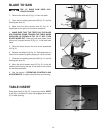
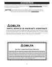
3. Check the upper blade guide assembly. The blade
guides (A) Fig. 54 should be parallel to the blade. To
adjust, loosen the screw (B) and rotate the complete
guide assembly (C). When the blade guides are parallel
with the blade, tighten the screw (B).
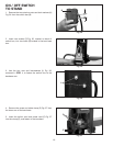
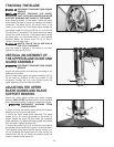
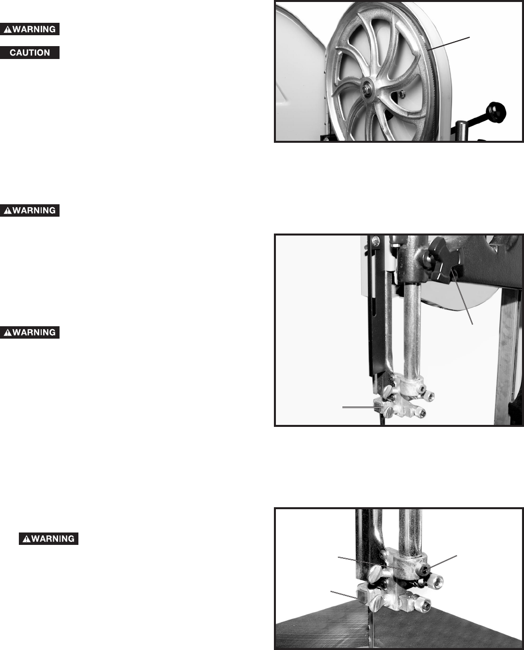
4. Adjust the guides (A) Fig. 55 so that the front edge of
the guides are just behind the “gullets” of the saw teeth.
The complete guide block bracket can be moved in or
out by loosening the thumb screw (C) and turning the
knurled knob (D) Fig. 55. When the guides (A) are set
properly, tighten thumb screw (C).
Fig. 54
A
C
B
B
A
A
1.