


7
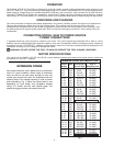
TABLE INSERT
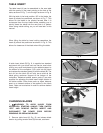
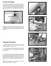
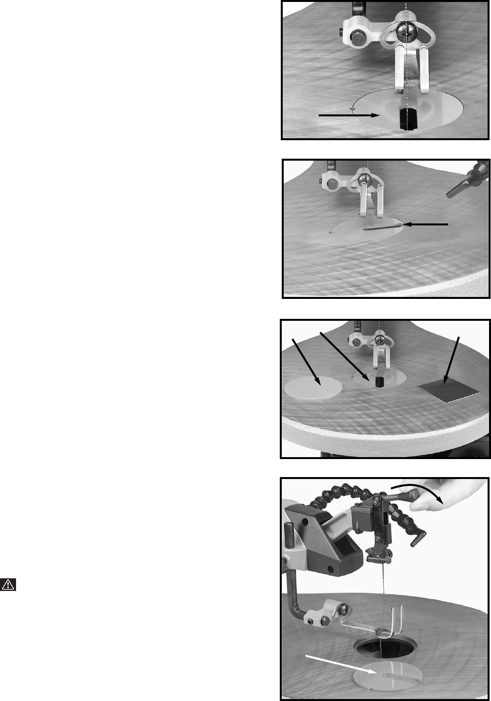
The table insert (A) can be assembled to the saw table
with the opening in the insert pointing to the front of the
table, as shown in Fig. 7, or to the right as shown in Fig. 8.
With the table in the level position, 90° to the blade, the
insert (A) should be positioned, as shown in Fig. 7. This
allows for the blade to be pivoted forward after it is
unclamped from the top blade holder, enabling you to
quickly insert the blade into the next hole in a pattern
when doing inside-cutting, as you will see later in this
manual.
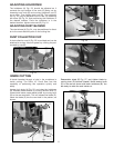
When tilting the table for bevel cutting operations the
insert (A) should be positioned as shown in Fig. 8. This
allows for clearance of the blade when tilting the table.
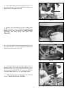
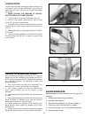
A table insert blank (B) Fig. 9, is supplied as standard
equipment with your scroll saw and can be used when
cutting very small workpieces to give added support to
the bottom of the workpiece. Cut a slot into the blank
and replace the standard insert (A) with the blank (B). The
slot cut into the blank (B) will only be as wide as the
blade giving maximum support to the bottom of the
workpiece. Adhesive backed spacer pads (C) are also
supplied for adjusting the table insert height relative to
the table surface. Place three pads an equal distance
apart on a cleaned surface to be applied to the blank
insert. Pads can be stacked in order to achieve desired
insert height.
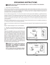
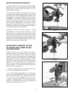
CHANGING BLADES
1. WARNING: TO AVOID INJURY FROM
ACCIDENTAL STARTING ALWAYS TURN SWITCH
“OFF” AND REMOVE SWITCH INSERT AND
DISCONNECT THE POWER CORD BEFORE
REMOVING OR REPLACING BLADE.
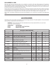
2. Remove table insert (A) Fig. 10, and release blade
tension by pulling tension lever (B) forward, as shown.
Fig. 7
Fig. 8
Fig. 9
A
A
B
A
C
Fig. 10
A
B