


9
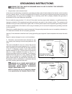
ADJUSTING BLADE TENSION
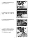
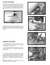
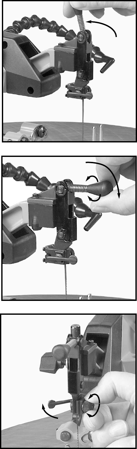
Tension is applied to the blade when the blade tension
lever (A) Fig. 15, is in the rear position, as shown. When
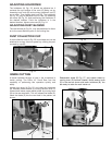
the lever (A) is moved forward, as shown in Fig. 16,
blade tension is released.
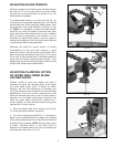
To increase blade tension, turn lever knob (B) Fig. 16,
clockwise and to decrease blade tension, turn knob (B)
counterclockwise. When adjusting blade tension, lever
(A) should be in the forward position, as shown in Fig.
16. NOTE: It is necessary to adjust the blade tension
knob (B) only when the blade is removed from both
upper and lower blade holders and a new or different
type of blade is assembled to the holders. It is not
necessary to adjust blade tension when the blade is
removed and replaced in only the upper blade holder as
in performing inside cutting operations.
Adjusting the blade for proper tension is usually
accomplished by trial and error; however, a good
method to use is to pluck the rear of the blade, like a
guitar string, after the tension lever (A) Fig. 15, is moved
to the rear. A high-pitched tone of the blade should be
heard and this usually indicates proper tension. Finer
blades require more tensioning (a higher pitched sound)
while thicker blades require less tension.
ADJUSTING CLAMPING ACTION
OF UPPER AND LOWER BLADE
HOLDER CHUCK
Different widths of scroll saw blades will make it
necessary to adjust the clamping action of the upper
and lower blade holder chuck. It should be noted,
however, that very little adjustment is necessary and
very little clamping force is required to hold the blade
satisfactorily. As a rule of thumb, looking down at the
table with the table insert slot in the 6 o’clock position,
resistance on the blade locking lever should be felt
when the upper blade locking lever reaches the 7
o’clock position, or when the lower blade locking lever
reaches the 5 o’clock position.
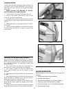
1. Move the blade holder chuck locking lever (A) Fig.
17, to the rear (open) position, as shown.
2. Turn chuck clamping knob (B) Fig. 17, clockwise to
tighten and counterclockwise to loosen the clamping
action of the blade holder chuck. Very little movement of
knob (B) will be necessary. NOTE: Only the upper chuck
is shown. Clamping action of the lower chuck is
adjusted in the same manner and can be accessed by
removing dust cup shown in Fig. 12.
Fig. 16
Fig. 17
Fig. 15
A
A
A
B
B