8
FACEPLATE
To reduce the risk of injury, tighten all
screws and levers securely when adjusting any part of
the lathe.
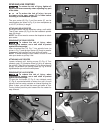
To reduce the risk of injury,
when using the
included 3" (76 mm) faceplate (B) Fig. 2, do not mount
pieces larger than 6" (152 mm) in diameter and up to 6"
(152 mm) in length. For mounting larger pieces, be sure
to use an appropriately sized faceplate.
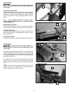
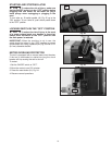
REMOVING FACEPLATE
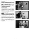
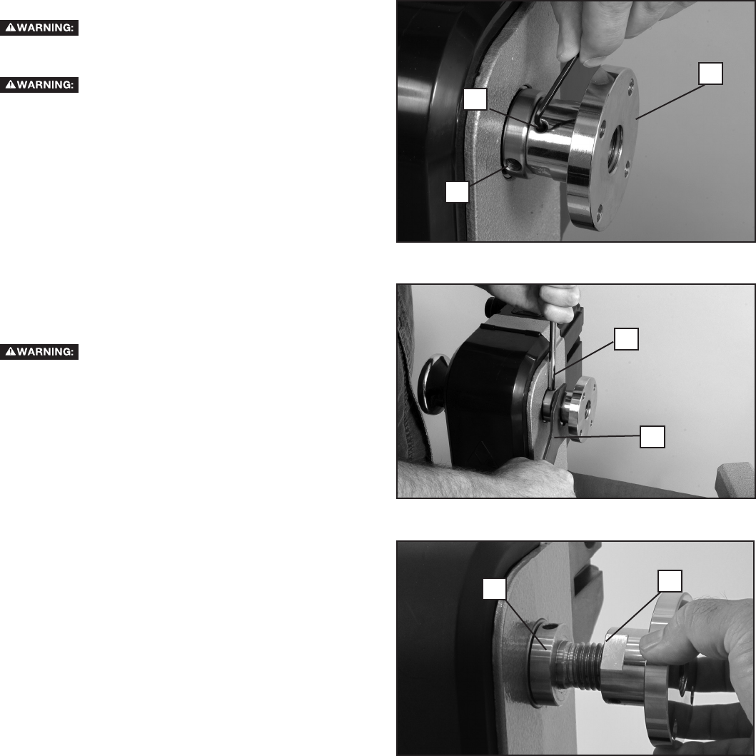
To remove the faceplate, use the included 3 mm hex
wrench to unlock the set screws (L) at least two full turns.
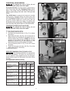
Place knockout bar (H) Fig. 3 in hole (M) Fig. 2 and place
faceplate wrench (I) Fig. 3 on faceplate shoulder ats (as
shown in Fig. 3) and turn wrench to loosen faceplate.
Once loose, the faceplate (B) Fig. 2 can be unscrewed.
REPLACING FACEPLATE
FOR THE DELTA
®
MODEL 46-460 MIDI-
LATHE ONLY: To reduce the risk of injury, if turning
in reverse, be sure to tighten the set screws (L) Fig. 2
securely when replacing the faceplate.
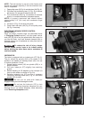
To re-attach faceplate (B) Fig. 4, screw it back on to the
spindle nose (K) and tighten securely using the knockout
bar and wrench as shown in gure 3. Replace set screws
(L) Fig. 2 if removed. Tighten set screws securely.
Directions for mounting a workpiece to the faceplate can
be found in the section Mounting the Workpiece under
MACHINE USE.
B
Fig. 3
Fig. 4
Fig. 2
H
B
L
M
I
K


