


11
OPERATING CONTROLS AND ADJUSTMENTS
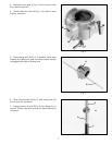
Fig. 23
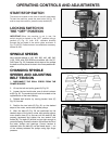
START/STOP SWITCH
The switch is located on the front of the drill press head.
To start the machine, press the start button (A) Fig. 23,
and to stop the machine, press the stop button (B).
LOCKING SWITCH IN
THE “OFF” POSITION
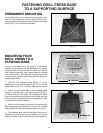
IMPORTANT: When the machine is not in use, the
switch should be locked in the “OFF” position using a
padlock (C) Fig. 24, (with 3/16 diameter shackle)
through the two holes in the switch plate, as shown in
Fig. 24. NOTE: Padlock shown is available as accessory
Model 50-325.
Fig. 24
Fig. 25
Fig. 26
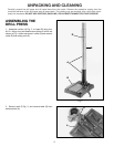
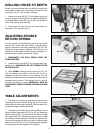
CHANGING SPINDLE
SPEEDS AND ADJUSTING
BELT TENSION
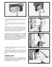
1. DISCONNECT THE DRILL PRESS FROM THE
POWER SOURCE.
2. Lift up the belt and pulley guard (A) Fig. 26.
3. Loosen the two lock knobs, one of which is shown
at (B) Fig. 26. The remaining lock knob is located on the
opposite side of the head casting.
4. Release belt tension by moving tension lever (C)
Fig. 26, forward.
5. Position the two belts (D) Fig. 26, on the desired
steps of the motor, center and spindle pulleys.
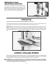
6. After the belts (D) Fig. 26, are positioned on the
desired steps of the motor, center and spindle pulleys,
move tension lever (C) to the rear until the belts (D) are
properly tensioned and tighten the two tension lock
knobs (B). The belts (D) should be just tight enough to
prevent slipping. Excessive tension will reduce the life of
the belts, pulleys and bearings. Correct tension is
obtained when the belts (D) can be flexed about 1 out
of line midway between the pulleys using light finger
pressure.
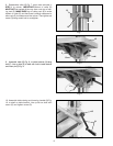
SPINDLE SPEEDS
Nine spindle speeds of 150, 260, 300, 440, 490, 540,
1150, 1550, and 2200 RPM are available with the 20
Drill Press. Fig. 25, illustrates which steps of the pulleys
the belts must be placed to obtain the nine speeds avail-
able.
SPINDLE CENTER MOTOR
440
300
150
1150
540
260
2200
1550
490
A
B
C
A
C
B
D
D