


7
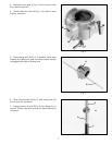
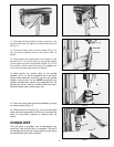
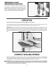
Fig. 4
3. Assemble worm gear (J) Fig. 4, to the inside of hole
(K) in table bracket (H).
4. Thread table lock lever (M) Fig. 4, into hole in table
bracket, as shown.
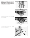
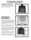
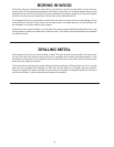
Fig. 5
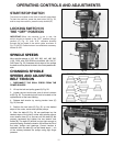
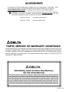
Fig. 6
5. Place raising rack (E) Fig. 5, in position inside table
bracket (H) making sure gear on inside of table bracket
is engaged with teeth of raising rack.
6. Slide table bracket (H) Fig. 6, with raising rack (E)
onto column (A), as shown.
7. Engage bottom of rack (E) Fig. 6, with flange (L) on
column. Tighten table lock lever to lock table bracket (H)
to column.
M
K
H
J
H
E
E
H
A
L