


12
Fig. 27
Fig. 28
Fig. 29
Fig. 30
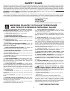
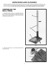
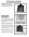
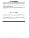
DRILLING HOLES TO DEPTH
Where a number of holes are to be drilled to exactly the
same depth, a depth stop is provided in the pinion shaft
housing (A) Fig. 27, and is used as follows:
1. Loosen lock lever (B) Fig. 27, and rotate housing (A)
until the pointer (C) lines up with the depth indicated on
the English/Metric scale (D) that you want the spindle to
lower. Then tighten lock lever (B).
2. The spindle will then lower to the exact depth as
indicated on the scale (D) Fig. 27
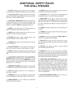
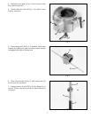
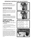
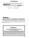
ADJUSTING SPINDLE
RETURN SPRING
For the purpose of automatically returning the spindle
upward after a hole has been drilled, a spindle return
spring is provided in the spring housing (A) Fig. 28. This
spring has been properly adjusted at the factory and
should not be disturbed unless absolutely necessary. To
adjust the return spring, proceed as follows:
1. DISCONNECT THE DRILL PRESS FROM THE
POWER SOURCE.
2. Loosen the two nuts (B) Fig. 28, approximately one-
quarter inch. IMPORTANT: DO NOT REMOVE NUTS
(B) FROM SHAFT.
3. While FIRMLY holding spring housing (A) Fig. 28,
pull out housing and rotate it until the roll pin (C) is
engaged with the next notch on the housing. Turn the
housing counterclockwise to increase and clockwise to
decrease spring tension. Then tighten the two nuts (B)
to hold the housing in place. IMPORTANT: NUTS (B)
SHOULD NOT CONTACT SPRING HOUSING (A) WHEN
TIGHT.
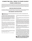
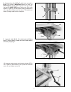
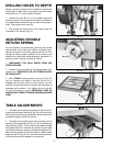
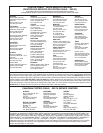
TABLE ADJUSTMENTS
1. The table can be raised or lowered on the column by
loosening table clamp handle (A) Fig. 29, and turning the
table raising and lowering handle (B). After the table is at
the desired height, tighten handle (A).
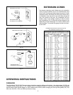
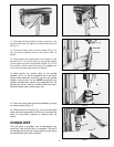
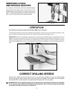
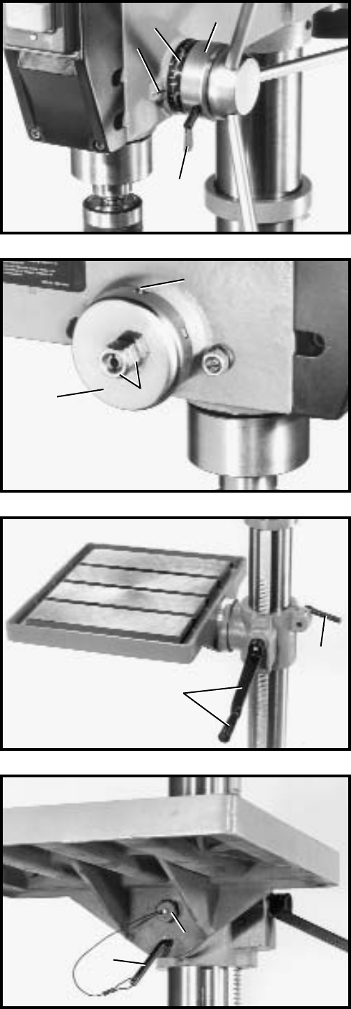
2. The table can be tilted right or left by pulling out and
removing table alignment pin (C) Fig. 30, and loosening
table locking bolt (D). Tilt the table to the desired angle
and tighten bolt (D). A tilt scale and pointer are provided
on the table bracket casting to indicate the degree of tilt.
When returning table to the level position, replace table
alignment pin (C) Fig. 30. This will automatically position
the table surface at 90 degrees to the spindle.
C
D
B
C
A
D
B
A
C
B
A