


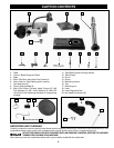
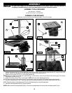
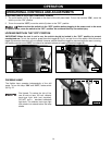
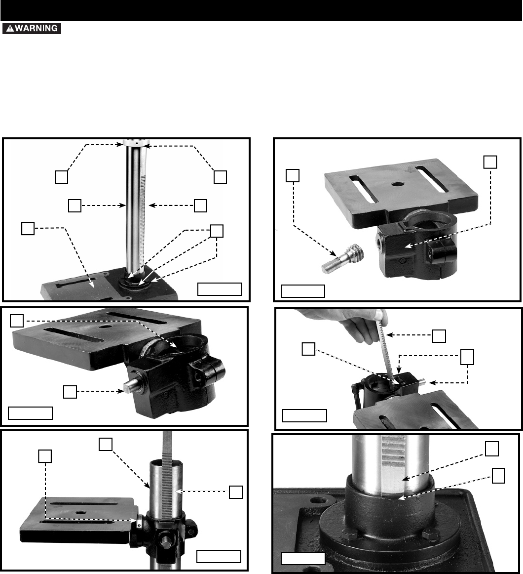
1. Attach the column (A) Fig. 3 to the base (B) using the four M8x1.25x25mm hex head screws (C), three of which are
shown. Loosen the set screw (D) and remove the ring (E) and raising rack (F).
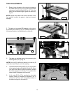
2. Place the worm gear (G) Fig. 4 in the table bracket (H).
NOTE: Place the small end of the worm gear (G) Fig. 5 in the hole (J), then into the hole for the worm gear. The correct
placement is shown in Fig. 5.
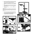
3. Insert the raising rack (F) Fig. 6 (removed in STEP 1) in the table bracket groove (I).
NOTE: Place the teeth of the raising rack (F) in the teeth of the worm gear (G) located inside table bracket.
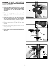
4. Slide the raising rack (F) Fig. 7 and the table with the table bracket (J) on the drill press column (K) Fig. 7.
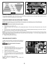
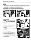
NOTE: Place the bottom of the raising rack (F) Fig. 8 inside the flange (L) on the drill press base.
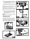
5. Place the mounting bracket (A) Fig. 10 on the column.
NOTE: Make sure the mounting bracket (A) Fig. 10 is on the opposite side of the column from the raising rack (F) Fig. 8.
For your own safety, do not connect the machine to the power source until the machine is
completely assembled and you read and understand the entire instruction manual.
A
E
F
D
C
B
Fig. 3
Fig. 4
Fig. 5
G
H
G
J
Fig. 6
Fig. 7
F
G
J
K
F
I
ASSEMBLY
ASSEMBLY TOOLS REQUIRED
Hex Wrenches - (supplied)
1/2 open end wrench - (not supplied)
ASSEMBLY TIME ESTIMATE
Assembly for this machine takes approximately 15 to 30 minutes.
F
L
Fig. 8
10