


17
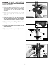
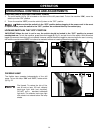
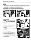
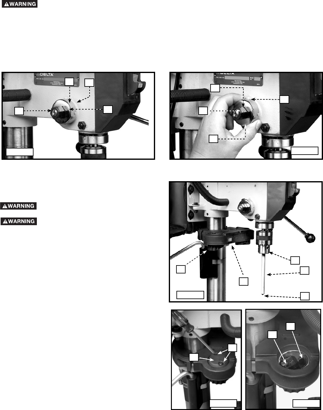
ADJUSTING SPINDLE RETURN SPRING
The spindle will automatically return slowly to its upper position when the handle is released. The spindle return spring
was properly adjusted at the factory. However, to adjust, if necessary:
1. Loosen the nuts (B) and (E) Fig. 31. Make sure that the spring housing (A) remains engaged with head casting (C).
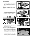
2. While firmly holding the spring housing (A) Fig. 32, pull out the housing and rotate it (counter-clockwise to
increase or clockwise to decrease the spring tension) until the boss (D) is engaged with the next notch on the
housing. Turn the nut (E) until it contacts the spring housing (A), then back the nut (E) out 1/4 turn from the spring
housing (A). Tighten the nut (B) against the nut (E) to hold the housing in place.
IMPORTANT: The inside nut (E) should not contact spring housing (A) when tightened.
Disconnect machine from power source.
Fig. 31
Fig. 32
A
B
E
D
E
B
A
C
Fig. L1
Fig. L2
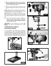
ADJUSTING LASERS
Disconnect machine from power
source.
Laser Light. Do not stare into the beam,
aperture, or into a reflection from a
mirror-like surface.
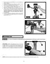
MAKING LASERS PARALLEL
1. Install alignment pin (A) into chuck (B). Make sure
that the pointed end (C) of the alignment pin is
down, as shown in Fig. L1. The black scribed line on
the pin should face towards the left laser.
2. Turn on lasers using switch (D) on the front of the
laser housing.
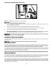
3. With a Phillips head screwdriver, remove the two
screws (F) Fig. L2 and cap (G) above the left side of
laser housing.
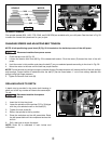
4. Loosen the laser retainer screw (H) Fig. L3.
5. Move the laser lever (I) Fig. L3 so the laser is shining
on the alignment pin. Adjust the lever (I) until the
laser is parallel with the black line.
NOTE: It may be necessary to move the laser holder (J)
Fig. L1 to get the laser to shine on the alignment pin.
Once the light is on the pin, adjust the laser with the
lever (I).
6. When laser is set, tighten the laser retainer screw (H)
Fig. L3. Then, replace the cap (G) Fig L2 and loosely
tighten the two screws (F).
7. Repeat for the right side.
MAKING LASERS INTERSECT
A
B
C
D
Fig. L3
F
G
H
I
J