


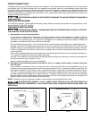
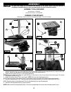
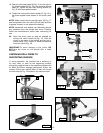
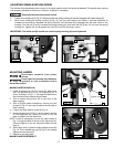
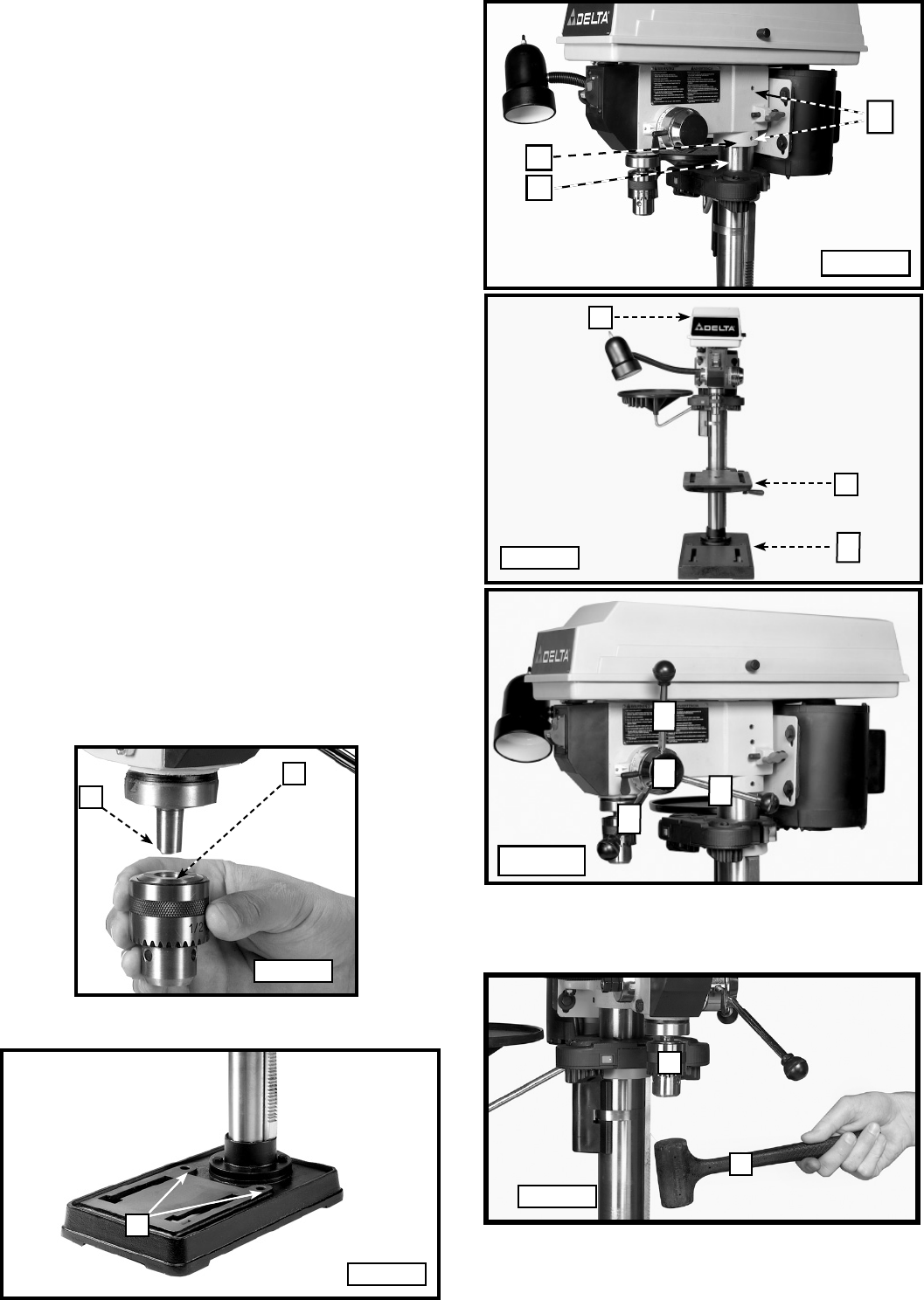
18. Seat the drill press head (N) Fig. 15 on the column
(U). Align the head (A) Fig. 15A, with the table (B) and
base (C). Tighten the two head locking screws (O)
Fig. 15 with the supplied wrench.
19. Thread the three pinion shaft handles (P) Fig. 16 in
the three tapped holes located in the pinion shaft
(S).
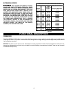
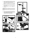
NOTE: Make certain that the spindle taper (Q) Fig. 17
and the tapered hole in the chuck (R) are clean and free
of grease, lacquer, or rust preventive coatings.
NOTE: Household oven cleaner can effectively remove
any substance from the spindle and chuck. Carefully
follow the manufacturer's safety rules concerning its
use.
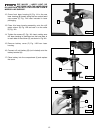
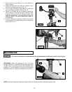
20. Open the chuck jaws as wide as possible by
turning the chuck sleeve (N) Fig. 18. Hold the
chuck on the taper of the spindle and tap with a
rubber mallet (T) or a block of wood and hammer
to set the chuck (Fig. 18).
IMPORTANT: To avoid damage to the chuck, DO
NOT drive the chuck on the spindle with a metal
hammer.
Fig. 15A
Fig. 17
Fig. 18
Fig. 15
N
U
O
A
B
C
Q
R
N
T
Fig. 16
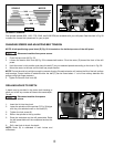
FASTENING DRILL PRESS TO
SUPPORTING SURFACE
If, during operation, the machine has a tendency to
tip over, slide, or walk on the supporting surface,
secure the machine base to the supporting surface with
an M8x1.25x125mm carriage head screw, 8.5mm flat
washer, 8.5mm lock washer, M8x1.25 hex nut through
the two holes (A) Fig. 19 located in the machine base.
Fig. 19
A
P
P
P
S
13