


15
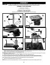
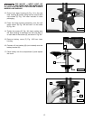
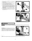
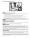
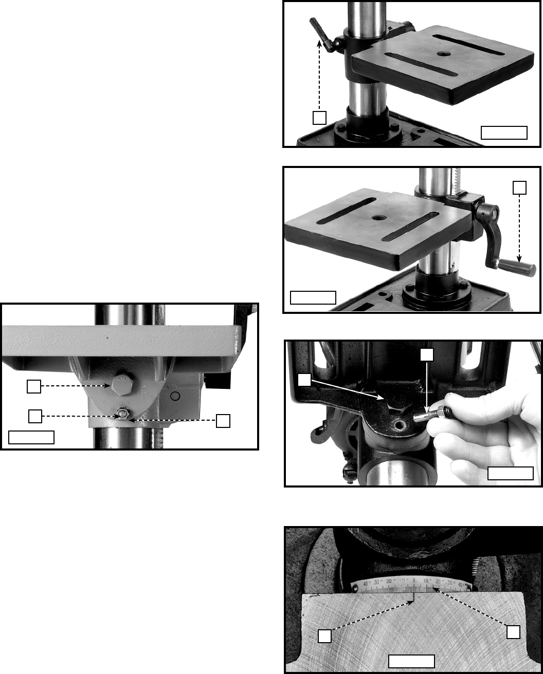
3. The table can be tilted right or left by removing the
table alignment pin (C) Fig. 25.
NOTE: If the pin (C) is difficult to remove, turn the nut (E)
clockwise to pull the pin out of the casting.
4. Loosen the table locking bolt (D) Fig. 26, tilt the table
to the desired angle, and tighten the bolt (D). When
you return the table to the level position, replace
the table alignment pin (C) Fig. 25 to position the
table surface 90 degrees to the spindle.
5. A tilt scale (E) Fig. 27 is provided on the table
bracket casting to indicate the degree of tilt. A
witness line and zero mark (F) are also provided on
the table to align with the scale (E).
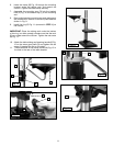
TABLE ADJUSTMENTS
1. Raise or lower the table on the column by loosening
the table clamp (A) Fig. 23, and turning the table
raising and lowering handle (B) Fig. 24. After the
table is at the desired height, tighten the clamp (A)
Fig. 23.
NOTE: Always raise (rather than lower) the table to the
final position to allow the gears to mesh and prevent
slippage.
2. The table can be rotated 360 degrees on the column
by loosening the clamp (A) Fig. 23, rotating the table to
the desired position, and tightening the clamp (A).
A
B
D
C
E
D
C
F
E
Fig. 23
Fig. 24
Fig. 25
Fig. 26
Fig. 27