


13
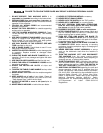
Fig. 25
H
D
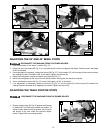
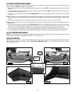
ADJUSTING THE 90° AND 45° BEVEL STOPS
DISCONNECT THE MACHINE FROM THE POWER SOURCE.
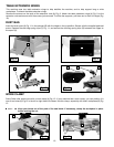
1. Lock the machine in the “down” position (Fig. 21).
2. Place one end of a square (B) Fig. 21 on the table and the other end against the blade. Check to see if the blade
is 90° to the table.
3. If an adjustment is necessary, loosen the locknut (B) Fig. 22. Turn the screw (C) until the head of the screw contacts
the casting (D) when the blade is 90° to the table. Tighten the locknut (B).
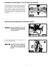
4. Raise the cuttinghead. Loosen the bevel lock handle (A) Fig. 21.
5. Move the cuttinghead all the way to the left bevel position and tighten the bevel lock handle.
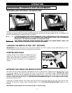
6. Use a combination square (A) Fig. 23 to see if the blade is at 45° to the table.
7. If an adjustment is necessary, loosen the locknut (E) Fig. 24. Turn the screw (F) until the screw (F) contacts the
casting (G) when the blade is 45 degrees to the table. Tighten the locknut (E).
A
Fig. 21
Fig. 22
Fig. 23
Fig. 24
A
C
B
E
F
B
D
G
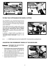
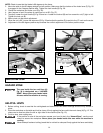
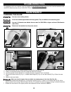
ADJUSTING THE TABLE POSITIVE STOPS
DISCONNECT THE MACHINE FROM THE POWER SOURCE.
1. Place a straight edge (D) Fig. 25 against both fences
to determine if the two fence halves are parallel. To
adjust, loosen fence mounting screws, two of which
are shown at (H) and make the required adjust-
ments. Tighten fence mounting screws.