


6
DESCRIPTION OF OPERATION (cont'd)
Outlet Pressure Gauge: The outlet pressure gauge indi-
cates the air pressure available at the outlet side of the
regulator. This pressure is controlled by the regulator and is
always less or equal to the tank pressure. See “Operating
Procedures”.
Tank Pressure Gauge: The tank pressure gauge indicates
the reserve air pressure in the tank.
Regulator: The air pressure coming from the air tank is
controlled by the regulator knob. Turn the knob clockwise to
increase pressure and counterclockwise to decrease pres-
sure. To avoid minor readjustment after making a change in
pressure setting, always approach the desired pressure from
a lower pressure. When reducing from a higher to a lower
setting, first reduce to some pressure less than that desired,
then bring up to the desired pressure. Depending on the air
requirements of each particular accessory, the outlet regu-
lated air pressure may have to be adjusted while you are
operating the accessory.
ASSEMBLY INSTRUCTIONS
Items Needed for Assembly
• a 9/16" socket or open-end wrench for attaching the
wheels
• a 3/8" open-end wrench to tighten handle screws
Installing Wheels, Handles, Rubber Foot Strip
It may be necessary to brace or support one end
of the outfit when attaching the wheels because
the air compressor will have a tendency to tip.
1. Remove the protective paper strip from the adhesive-
backed rubber foot strip. Attack the rubber foot strip to
the bottom of the air tank leg. Press firmly into place.
2. The leg bracket on the underside of the air compressor
tank has 2 holes on each side for mounting the wheels.
Place one shoulder bolt through the hole in a wheel. On
models with 10" wheels, push the bolt through the TOP
hole of the leg bracket. For models with 8" wheels, push
the bolt through the BOTTOM hole of the leg bracket.
Screw on one hex locking nut. The special locking nut
does not turn freely. Tighten the nut firmly until it contacts
the tank leg. The outfit will sit level if the wheels are
properly installed.
NOTE
The side of the wheel, that the hub protrudes
out past the wheel edge, should be bolted to the
compressor leg.
THE WHEELS AND HANDLE DO NOT PROVIDE
ADEQUATE CLEARANCE, STABILITY OR SUP-
PORT FOR PULLING THE UNIT UP AND DOWN
STAIRS OR STEPS. THE UNIT MUST BE LIFTED
OR PUSHED UP A RAMP. DO NOT LIFT THE UNIT
BY THE MANIFOLD ASSEMBLY. THE UNIT CAN
BE DAMAGED.
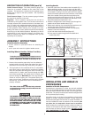
Installing Handle
1. Insert the open end of the handle under the saddle (Fig. 1).
Before attaching handle, you may have to pull the open
ends of the handle apart so they fit tightly against the side
of the saddle. Looking in from the open end of the saddle,
position the handle toward the two bent tabs, on the inside
walls of the saddle. Slowly push the open ends of the
handle onto both tabs at the same time (Fig. 2). Continue
pushing the handle into the saddle until the holes on the
side of the saddle and handle are in line.
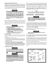
2. Guide the straight end of each retaining clip through the
saddle hole and both handle holes (Fig. 3).
3. Rotate each retaining clip clockwise and press down until
it snaps into place over the pull handle (Fig. 4).
4. If the handle has excessive movement, it is improperly
installed. Check the following.
A. Are both tabs inside the handle (Step #1)?
B. Does each clip pass through both the saddle and
handle (Step #2)?
INSTALLATION AND BREAK-IN
PROCEDURES
Location of the Air Compressor
Operate the air compressor in a clean, dry and well ventilated
area. The fan bladed flywheel must be kept clear of obstruc-
tions that could interfere with the flow of air through the air
intake filter. The pump crankcase and head are designed with
fins to provide proper cooling.
If humidity is high, an air filter can be installed on the air outlet
adapter to remove excessive moisture. Closely follow the
instructions packaged with the filter for proper installation. It
must be installed as close as possible to the accessory.Do
not place the air compressor where heat is excessive.
When locating the compressor outside, make sure there is a
mimum of 12 inches on each side of the compressor. There
must be fresh air flow for proper cooling. DO NOT ALLOW
THE COMPRESSOR TO GET WET.
FIG. 1
FIG. 3
FIG. 2
FIG. 4