


10
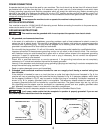
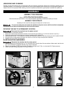
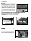
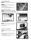
Attach the left extension wing (A) Fig. 9 to the saw table. Align
the three holes in the extension wing with the three holes (A) Fig.
9 in the side of the saw table. Place a 7/16" lockwasher and a
7/16" flat washer on a 7/16-20 x 1-1/4” hex head screw (B) Fig.
9). Insert the screw through the hole in the extension wing and
thread the screw into the tapped hole in the side of the table.
Repeat this process for the two remaining holes in the extension
wing and saw table.
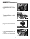
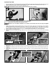
Use a straight edge (E) Fig. 11 to level the extension wing (A) with
the saw table before tightening three bolts (B) Fig. 10. Use an
18mm open-end wrench and start with a bolt on one side. Align
the table and wing and tighten that bolt. Move to the middle bolt
and follow the same procedure. Finish with the bolt on the other
end.
NOTE: Ensure that the front edge of the wing is flush with or slightly behind the front edge of the table.
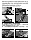
Place the right extension wing on the other side of the saw in the same manner.
Do not operate the saw without right table wing installed.
EXTENSION WINGS
Disconnect the machine from the power source!
B
A
A
E
Fig. 9
Fig. 10 Fig. 11
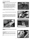
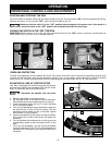
INSTALLING THE SWITCH
Disconnect the machine from the power source!
Fig. 12
Attach the switch behind the table edge with the hardware
(supplied with the fence). The screw that fastens the front
fence rail will secure the switch by going though the hole (A)
Fig. 12 in the table edge and the hole (B) in the switch.
A
B
Fig. 12
B