


12
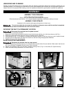
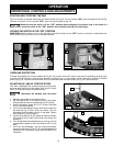
Always return the guard to the "down" position before operating the saw.
Do not operate the saw without the table insert and guard in place.
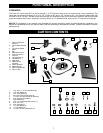
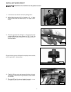
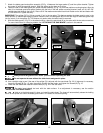
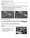
7. Attach the blade guard and splitter assembly (G) Fig. 19 between the large washer (C) and the splitter bracket. Tighten
the screw (H) with the supplied wrench. Slide the splitter as far down as it will go.
8. Fasten the rear of the blade guard and splitter bracket assembly (G) Fig. 19 to the rear splitter mounting bracket. Align the
hole (J) in the blade guard and splitter bracket with the hole in the rear splitter mounting bracket. Insert a 5/16-18 x 5/8"
carriage head bolt through the hole (J). Place a 5/16" flat washer and external tooth lock washer on the bolt and fasten with
a 5/16-18 hex nut. Tighten securely.
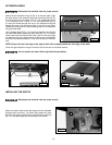
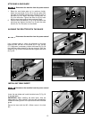
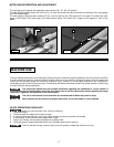
IMPORTANT: The splitter (G) Fig. 20 has a notch (L) cut in the top edge. This feature enables the blade guard to stay in the
raised position to make blade changing easier. Raise the front of blade guard (M) until the rear edge of the blade guard slips
into the notch (L) of the splitter (G). This feature only works when the table insert is removed.
9. With the blade guard (L) Fig. 21 in the raised position, attach the saw blade (K) on the arbor with the two arbor wrenches.
For more instructions on changing blades, see “ATTACHING THE SAW BLADE” section in this manual.
G
H
C
L
G
K
Fig. 19
Fig. 21
Fig. 22
G
L
R
Fig. 23
Fig. 24
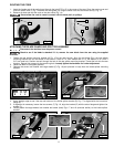
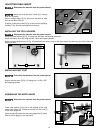
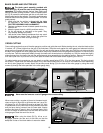
10. Use a straight edge to see if the rear of the splitter (G) is aligned with the saw blade (Fig. 23). If alignment is necessary,
loosen the screws (B) Fig. 15, align the splitter (G) with the saw blade, and tighten the screws (B) Fig. 15.
11. Lower the saw blade and install the table insert (R) Fig. 24 in the saw table.
The table insert should be level with the table surface. If an adjustment is necessary, see the section
"ADJUSTING THE TABLE INSERT".
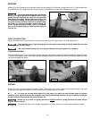
Hold on to the blade guard (L) when you install the table insert. The insert will automatically release the holding
action of the splitter and lower the blade guard when it is installed in the table opening.
L
G
J
Fig. 20