


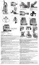
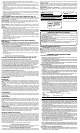
COMPONENTS (FIG. 1)
A. ON-OFF Switch
B. Base Locking Screw
C. Spindle Lock
D. Collet Nut
E. Base
F. Sub-Base
G. Depth Adjusting Wheel
Starting and Stopping Motor (Fig. 1)
The ON/OFF switch (A) is located on the side of the unit, close to the top. To start the router,
move the switch down to the ON position. To stop the router, move the switch up to the OFF
position.
Prior to plugging in the tool, make sure that the switch is in the OFF position and that the power
circuit voltage is the same as that shown on the specification plate of the router.
WARNING: To reduce the risk of personal injury or tool damage, grasp router firmly to resist
starting torque and make sure bit is clear of workpiece and foreign objects.
WARNING: To reduce the risk of personal injury or damage to finished work always allow the
motor to come to a COMPLETE STOP before setting router down.
Standard and Tilt Bases (Fig. 1, 2)
INSTALLING THE BIT
WARNING: To reduce the risk of injury, turn unit off and disconnect it from power
source before installing and removing accessories, before adjusting or when making
repairs. An accidental start-up can cause injury.
WARNING: Projectile hazard. Only use bits with 1/4" (6.4 mm) shanks. Smaller shank bits will
not be secure and could become loose during operation.
CAUTION: To avoid damaging your router, do not tighten the collet without a bit inserted.
CAUTION: To avoid damaging your router, do not press spindle lock button while the motor is
running.
NOTE: It is recommended that the unit only be used with bits that have a cutting diameter of
13/16" (20.6 mm) or less.
NOTE: Directions for installing bits in the offset base are included later in this manual.
1. You can install bits with the motor unit attached or removed.
2. Depress the spindle lock (C) and rotate the collet nut (D) by hand until the lock engages the
hole in the motor spindle. Loosen the collet nut (D) slightly.
3. Clean and insert the shank of the bit (H) into the collet until the end of the shank bottoms.
Then withdraw the bit approximately 1/16" (1.6 mm).
4. While holding the spindle lock, use the provided open-end wrench to tighten the collet nut
(clockwise) securely.
REMOVING THE BIT
WARNING: To reduce the risk of injury, turn unit off and disconnect it from power
source before installing and removing accessories, before adjusting or when making
repairs. An accidental start-up can cause injury.
WARNING: Burn hazard. Do not touch the router bits immediately after use.
CAUTION: To avoid damaging your router, do not press spindle lock button while the motor is
running.
NOTE: Directions for removing bits in the offset base are included later in this manual.
1. You can remove bits either with the motor unit attached or removed.
2. Depress the spindle lock (C) and rotate the collet nut (D) by hand until the lock engages the
hole in the motor spindle.
3. While holding the spindle lock engaged, loosen the collet nut (D) by turning it counterclock-
wise with the provided open-end wrench.
4. If the bit (H) is tight on the collet, tap the collet nut (D) with a wrench to release the bit.
ADJUSTING THE DEPTH OF CUT (FIG. 1)
WARNING: To reduce the risk of injury, turn unit off and disconnect it from power
source before installing and removing accessories, before adjusting or when making
repairs. An accidental start-up can cause injury.
1. Loosen the base-locking screw (B) approximately 1/4 turn.
2. Turn the depth-adjusting wheel (G) to reduce or increase the depth of cut.
3. Tighten the base-locking screw (B) securely. Make a test cut in scrap material to check the
depth of cut.
4. Repeat steps 1 through 3 until the desired depth of cut is achieved.
For the tilt base, you may have to slightly withdraw some bits in the collet to obtain a maximum
depth of cut.
FIG. 6
Sub-base is shown turned over.
Sous-base est montré retourné.
Subbase se demuestra al revés.
3/16" (4.8 mm)
FIG. 5
FIG. 2
I
J
L
K
M
A
B
C
D
G
E
F
FIG. 1
H
N
O
P
Q
N
S
T
U
R
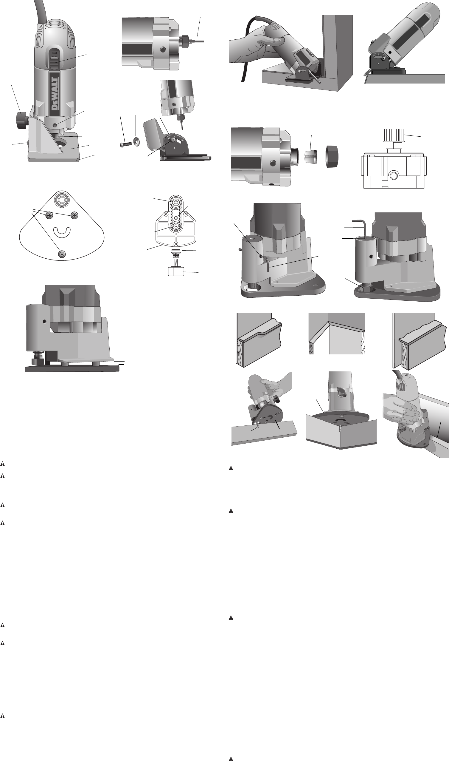
Trims up to vertical surfaces.
Taillage de surfaces verticales.
Cortes hasta superficies verticales.
FIG. 4
W
V
FIG. 9
FIG. 10
X
Y
Z
FIG. 11
FIG. 12
FIG. 13
FIG. 14
FIG. 15
FIG. 16
FIG. 17
DD
CC
BB
AA
WARNING: When you withdraw a bit, be certain that at least 1/2" (1.3 cm) of the bit shank is
engaged in the collet. Do not use bits that result in having less than 1/2" (1.3 cm) of the bit shank
engaged in the collet. To do so may cause poor gripping of the collet, resulting in a loose bit. If
the bit comes out of the collet, it could cause damage to the workpiece and/or personal injury.
Adjusting the Sub-Base Alignment for
Standard and Tilt Bases (Fig. 1)
WARNING: To reduce the risk of injury, turn unit off and disconnect it from power
source before installing and removing accessories, before adjusting or when making
repairs. An accidental start-up can cause injury.
Applications using a template guide require the bit to be centered within the guide, and the
center hole in the sub-base to be in line with the collet of the motor unit. Your model has an
adjustable sub-base (F). To adjust:
1. Install the desired template guide on the sub-base and tighten securely.
2. Loosen the sub-base mounting screws just enough to allow the sub-base to move on the
base (E). The base movement will be very slight.
3. Install a straight 1/4" (6.4 mm) diameter bit in the collet of the motor unit and tighten securely.
4. Attach the motor unit to the base. Align the hole in the template guide with the bit and adjust
the depth of cut so that the bit extends through the template guide. Tighten the motor unit in
the base.
5. Tighten the sub-base mounting screws securely.
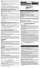
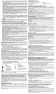
Tilt Base Assembly (Fig. 1, 3)
The tilt base is designed for use with flush trim bits for trimming into corners. You may also use
it with other self-pilot trim bits for conventional trimming at 90° setting.
WARNING: To reduce the risk of injury, turn unit off and disconnect it from power
source before installing and removing accessories, before adjusting or when making
repairs. An accidental start-up can cause injury.
TO ASSEMBLE THE TILT BASE (FIG. 1, 3)
1. Remove the standard base (if necessary) by removing screw (B), washer and spring (not
shown).
2. Attach the tilt base using screw (I) and flat washer (J) included with the tilt base.
TO ADJUST THE TILT (FIG. 1, 3)
1. Loosen two tilt locking screws (L) (one on each side of base) using the provided hex
wrench.
2. Match the base-aligning index mark (K) with the desired angle and tighten securely.
3. Make a trial cut on scrap material to check the alignment.
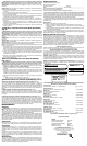
Typical Applications with Tilt Base (Fig. 4)
The tilt base is designed for these typical operations:
1. Trimming up to vertical surfaces.
2. Trimming odd angled corners less than or greater than 90°.
Offset Base Assembly (Fig. 2, 5–9)
The offset base allows trimming in tight spaces (the front edge of vertical backsplashes, inside
corners, etc.) and easy scribing of backsplashes to a wall.
To attach the offset base, first remove the standard base (if necessary) by removing screw (B),
washer and spring. Then, attach the offset base using these instructions:
WARNING: To reduce the risk of injury, turn unit off and disconnect it from power
source before installing and removing accessories, before adjusting or when making
repairs. An accidental start-up can cause injury.
Trims odd angled corners less than or
greater than 90°.
Taillage d’angles spéciaux inférieurs ou
supérieurs à 90°.
Cortes de extremos en ángulo menores
o mayores a 90°.
FIG. 3
FIG. 7
FIG. 8