


CAUTION: To avoid damaging your router, do not tighten the collet without a bit inserted.
CAUTION: To avoid damaging your router, do not press spindle lock button while the motor is
running.
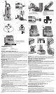
1. Depress spindle lock (C) and unscrew and remove the collet nut (D) and collet (M) from the
motor unit.
2. Attach the drive pulley (N) to the motor spindle. Screw in securely.
3. Use a Phillips screwdriver to remove the three sub-base mounting screws (O) from the
base. Remove the sub-base.
4. Position the base (R) on the drive pulley (N) (from step 2). Be sure that the motor drive pul-
ley engages the drive belt inside the base housing.
5. Secure the motor to the base with the thumbscrew (U), spring (T), and washer (S).
6. Use a Phillips screwdriver to install a #6-32 x 3/8" screw in the hole (Q). Tighten securely.
7. Clean the collet nut and collet (from step 1), and attach to the spindle (P) in the offset base.
Use hex wrench (W) in hole (V) to lock spindle. Hand tighten for further adjustment.
8. Position the sub-base to the base housing and secure with the three screws (O) that were
removed in step 3.
To Install & Remove Bit (Offset Base) (Fig. 9)
WARNING: To reduce the risk of injury, turn unit off and disconnect it from power
source before installing and removing accessories, before adjusting or when making
repairs. An accidental start-up can cause injury.
WARNING: Projectile hazard. Only use bits with 1/4" (6.4 mm) shanks. Smaller shank bits will
not be secure and could become loose during operation.
CAUTION: To avoid damaging your router, do not tighten the collet without a bit inserted.
CAUTION: To avoid damaging your router, do not press spindle lock button while the motor is
running.
CAUTION: To avoid damaging the drive belt, never tighten or loosen the collet nut with the
motor unit’s spindle lock engaged.
NOTE: It is recommended that the unit only be used with bits that have a cutting diameter of
13/16" (20.6 mm) or less.
1. To lock spindle on the offset base, insert the long portion of the hex wrench (W) through
the spindle lock hole (V), so that the wrench protrudes from both sides of the base housing.
For help inserting the hex wrench, rotate the spindle by hand to align the hole in the spindle
with the holes in the housing.
2. Clean and insert the bit shank into the collet until the end of the shank bottoms. Then with-
draw the bit approximately 1/16" (1.6 mm). Tighten the collet nut securely with the collet
wrench.
3. To remove the bit, reverse the procedure. If the bit will not remove easily, lightly tap the bit
shank with a wrench.
4. Remove hex wrench (W).
Adjusting Depth of Cut (Offset Base) (Fig. 10, 11)
WARNING: To reduce the risk of injury, turn unit off and disconnect it from power
source before installing and removing accessories, before adjusting or when making
repairs. An accidental start-up can cause injury.
1. Turn the router on its side and loosen the collet nut slightly. See To Install & Remove Bit
(Offset Base).
2. Place the hex wrench (X) in the hole (Y) to access the depth-adjusting screw.
3. Hold the spindle (Z) in place and apply light upward pressure on the bit to maintain contact
between the bit shank and the adjusting screw. Turn the hex wrench counter-clockwise to
increase exposure and clockwise to decrease exposure.
4. To turn the sub-base over to allow more clearance (3/16" or 4.8 mm) for long-shank bits (Fig.
11):
a. Remove three sub-base mounting screws (O).
b. Turn sub-base over and re-attach using screws removed in step a.
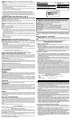
Typical Applications with Offset Base (Fig. 12–17)
TRIMMING 3/4" (19 mm) VERTICAL BACKSPLASH (FIG. 12, 13)
Trimming the front edge of 3/4" (19 mm) vertical backsplash (Fig.13) is an operation standard
routers with round or square bases are unable to do without the use of a special bit. The
operation is made easy with the offset base fitted with a solid carbide self-piloted bit. The
self-piloted bit (AA) allows one-pass trimming. The triangular base (BB) enables trimming with
backsplash in place.
IN-AND-OUT TRIMMING OF INSTALLED CORNER (FIG. 14, 15)
The offset base can also trim into and out of an installed backsplash corner (Fig. 15) with little
or no hand trimming required. Combining a self-piloted bit and a triangular base (CC) enables
complete corner trimming with backsplash in place.
SCRIBING OF BACKSPLASH TO WALL (FIG. 16, 17)
The offset base can accurately scribe the back side of a preassembled panel or post-formed
backsplash (Fig. 17). Once the back lip is accurately scribed, the trimmed portion is then
pushed against the wall and mated exactly. As the front edge of the router is guided against
the wall (Fig. 17), the router creates an exact reproduction of the wall surface in one pass.
Use a 3/4" (19 mm) spacer to maintain a 3/4" (19 mm) distance (DD) from the wall and the
back of the backsplash being cut.
MAINTENANCE
Cleaning
WARNING: Blowing dust and chips out of the motor housing using clean, dry compressed air
is a necessary regular maintenance procedure. Dust and chips containing metal particles often
accumulate on interior surfaces and could create an electrical shock or electrocution if not fre-
quently cleaned out. ALWAYS WEAR SAFETY GLASSES.
CAUTION: When cleaning, use only a damp cloth on plastic parts. Many household cleaners
contain chemicals which could seriously damage plastic. Also, do not use gasoline, turpentine,
lacquer or paint thinner, dry cleaning fluids or similar products which may seriously damage plas-
tic parts. Never let any liquid get inside the tool; never immerse any part of the tool into a liquid.
Lubrication
This tool has been lubricated with a sufficient amount of high-grade lubricant for the life of this
unit under normal conditions. No further lubricaton is necessary.
Accessories
WARNING: Since accessories, other than those offered by DEWALT, have not been tested
with this product, use of such accessories with this tool could be hazardous. To reduce the risk
of injury, only D
EWALT, recommended accessories should be used with this product.
Recommended accessories for use with your tool are available at extra cost from your local
service center. If you need any assistance in locating any accessory, please contact D
EWALT
Industrial Tool Co., 701 East Joppa Road, Baltimore, MD 21286, call 1-800-4-D
EWALT (1-800-
433-9258) or visit our website www.dewalt.com.
Repairs
To assure product SAFETY and RELIABILITY, repairs, maintenance and adjustment (including
brush inspection and replacement) should be performed by a D
EWALT factory service center,
a D
EWALT authorized service center or other qualified service personnel. Always use identical
replacement parts.
Three Year Limited Warranty
DEWALT will repair, without charge, any defects due to faulty materials or workmanship for three
years from the date of purchase. This warranty does not cover part failure due to normal wear
or tool abuse. For further detail of warranty coverage and warranty repair information, visit www.
dewalt.com or call 1-800-4-D
EWALT (1-800-433-9258). This warranty does not apply to acces-
sories or damage caused where repairs have been made or attempted by others. This warranty
gives you specific legal rights and you may have other rights which vary in certain states or
provinces.
In addition to the warranty, D
EWALT tools are covered by our:
1 YEAR FREE SERVICE
D
EWALT will maintain the tool and replace worn parts caused by normal use, for free, any time
during the first year after purchase.
90 DAY MONEY BACK GUARANTEE
If you are not completely satisfied with the performance of your D
EWALT Power Tool, Laser, or
Nailer for any reason, you can return it within 90 days from the date of purchase with a receipt
for a full refund – no questions asked.
LATIN AMERICA: This warranty does not apply to products sold in Latin America. For products
sold in Latin America, see country specific warranty information contained either in the packag-
ing, call the local company or see website for warranty information.
FREE WARNING LABEL REPLACEMENT: If your warning labels become illegible or are miss-
ing, call 1-800-4-DEWALT for a free replacement.
Défi nitions : lignes directrices en matière de sécurité
Les définitions ci-dessous décrivent le niveau de gravité pour chaque symbole. Veuillez lire
le mode d’emploi et porter une attention particulière à ces symboles.
DANGER : Indique une situation dangereuse imminente qui, si elle n’est pas évitée,
causera la mort ou des blessures graves.
AVERTISSEMENT :
Indique une situation potentiellement dangereuse qui, si elle n’est
pas évitée, pourrait se solder par un décès ou des blessures graves.
MISE EN GARDE : Indique une situation potentiellement dangereuse qui, si elle n’est pas
évitée pourrait se solder par des blessures mineures ou modérées.
MISE EN GARDE : Utilisé sans le symbole d’alerte à la sécurité, indique une situation poten-
tiellement dangereuse qui, si elle n'est pas évitée pourrait se solder par des dommages
à la propriété.
POUR TOUT RENSEIGNEMENT SUPPLÉMENTAIRE SUR CET OUTIL OU TOUT AUTRE
OUTIL D
EWALT, COMPOSER SANS FRAIS LE NUMÉRO : 1-800-4-DEWALT (1-800-433-
9258)
Règles de sécurité – Généralités
AVERTISSEMENT : Lire toutes ces directives. Tout manquement aux directives
suivantes pose des risques de choc électrique, d’incendie et/ou de blessure grave.
Le terme « outil électrique » dans tous les avertissements ci-après se rapporte à votre
outil électrique à alimentation sur secteur (avec fil) ou par piles (sans fil).
CONSERVER CES DIRECTIVES
1) SÉCURITÉ - AIRE DE TRAVAIL
a) Maintenir l’aire de travail propre et bien éclairée. Les lieux encombrés ou sombres sont
propices aux accidents.
b) Ne pas faire fonctionner un outil électrique dans une atmosphère explosive, en
présence par exemple de poussières, gaz ou liquides inflammables. Les outils élec-
triques peuvent engendrer des étincelles qui pourraient enflammer toute émanation ou
poussière ambiante.
c) Tenir les enfants, ou toute autre personne, éloignés pendant l’utilisation d’un outil
électrique. Toute distraction pourrait vous faire perdre la maîtrise de ce dernier.
2) SÉCURITÉ – ÉLECTRICITÉ
a) La fiche électrique de l’outil doit correspondre à la prise murale. Ne jamais modi-
fier la fiche en aucune façon. Ne jamais utiliser de fiche d’adaptation avec un outil
électrique mis à la terre. L’utilisation de fiches d’origine et de prises appropriées réduira
les risques de choc électrique.
b) Éviter tout contact corporel avec des éléments mis à la terre comme tuyaux, radia-
teurs, cuisinières ou réfrigérateurs. Les risques de choc électrique augmentent lorsque
le corps est mis à la terre.
c) Ne pas exposer les outils électriques à la pluie ou à l’humidité. Toute pénétration d’un
outil électrique par un liquide augmente les risques de choc électrique.
d) Ne pas utiliser le cordon de façon abusive. Ne jamais utiliser le cordon pour trans-
porter, tirer ou débrancher un outil électrique. Protéger le cordon de la chaleur,
de l’huile et de tout bord tranchant ou pièce mobile. Les cordons endommagés ou
emmêlés augmentent les risques de choc électrique. Remplacer ou faire réparer tout
cordon endommagé. S’assurer que la rallonge est en bon état. N’utiliser que des rallonges
trifilaires munies de fiches tripolaires et des prises tripolaires acceptant la fiche de l’outil.
e) Lors de l’utilisation d’un outil électrique à l’extérieur, n’utiliser que des rallonges con-
çues pour l’extérieur. L’utilisation d’une rallonge conçue pour l’extérieur réduit les risques de
choc électrique. En cas d’utilisation d’une rallonge, s’assurer que les valeurs nominales de
la rallonge utilisée correspondent bien à celles de l’outil alimenté. L’usage d’une rallonge de
calibre insuffisant causera une chute de tension entraînant perte de puissance et surchauffe.
Le tableau ci-dessous illustre les calibres à utiliser selon la longueur de rallonge et l’intensité
nominale indiquée sur la plaque signalétique. En cas de doutes, utiliser le calibre suivant. Plus
le calibre est petit, plus la rallonge peut supporter de courant.
Calibre mínimo para cordones de extensión
Volts Longitud total del cordón en metros
120V 0-7,6 7,6-15,2 15,2-30,4 30,4-45,7
Amperaje
Más No más Calibre del cordón AWG
de de
0 - 6 18 16 16 14
3) SÉCURITÉ PERSONNELLE
a) Rester vigilant en tout temps et faire preuve de jugement pendant l’utilisation d’un
outil électrique. Ne pas utiliser d’outil électrique en cas de fatigue ou sous l’influence
de drogues, d’alcool ou de médicaments. Tout moment d’inattention pendant l’utilisation
d’un outil électrique pose des risques de blessure grave.
b) Utiliser le matériel de sécurité approprié. Toujours porter des lunettes de protection.
Le fait de porter un masque anti-poussières, des chaussures antidérapantes, un casque
de sécurité ou des protecteurs auditifs lorsque la situation le requiert réduira les risques
de blessure.
c) Éviter tout démarrage accidentel. S’assurer que l’interrupteur est en position d’arrêt
avant tout branchement. Transporter un outil le doigt sur l’interrupteur ou brancher un
outil électrique alors que l’interrupteur est en position de marche invite les accidents.
d) Retirer toute clé de réglage avant de démarrer l’outil. Une clé laissée sur une pièce
rotative d’un outil électrique pose des risques de blessure.
e) Ne pas effectuer de travaux hors de portée. Les pieds doivent rester bien ancrés au
sol afin de maintenir son équilibre en tout temps. Cela permet de mieux maîtriser l’outil
électrique dans les situations imprévues.
f) Porter des vêtements appropriés. Ne pas porter de vêtements amples ni de bijoux.
Maintenir cheveux, vêtements et gants éloignés des pièces mobiles. Vêtements
amples, bijoux ou cheveux longs risquent de rester coincés dans ces pièces mobiles.
Prendre des précautions autour des évents car ils recouvrent des pièces mobiles.
g) Lorsque un dispositif de connexion à un système de dépoussiérage ou d’élimination
est fourni, s’assurer qu’il est connecté et utilisé correctement. L’utilisation de ces dis-
positifs peut réduire les risques engendrés par les poussières.
4) UTILISATION ET ENTRETIEN DES OUTILS ÉLECTRIQUES
a) Ne pas forcer un outil électrique. Utiliser l’outil approprié au travail en cours. L’outil
approprié effectuera un meilleur travail, de façon plus sûre et à la vitesse pour laquelle il a
été conçu.
b) Ne pas utiliser un outil électrique dont l’interrupteur est défectueux. Tout appareil
dont l’interrupteur est défectueux est dangereux et doit être réparé.
c) Débrancher la fiche du secteur et/ou le bloc-piles de l’outil électrique avant de
faire tout réglage ou changement d’accessoire, ou avant de ranger ce dernier. Ces
mesures préventives réduisent les risques de démarrage accidentel de l’appareil.
d) Après usage, ranger les outils électriques hors de la portée des enfants, et ne
permettre à aucune personne n’étant pas familière avec un outil électrique (ou son
manuel d’instruction) d’utiliser ce dernier. Les outils peuvent être dangereux entre les
mains des novices.
D26670
HEAVY-DUTY COMPACT ROUTER
DEWALT INDUSTRIAL TOOL CO., BALTIMORE, MD 21286 USA FOR SERVICE INFORMATION, CALL 1-800-4-DEWALT www.DEWALT.com
TO REDUCE THE RISK OF INJURY, USER MUST READ INSTRUCTION MANUAL. ALWAYS USE PROPER
EYE AND RESPIRATORY PROTECTION. PARA EL MANEJO SEGURO LEA EL MANUAL DE
INSTRUCCIONES. SIEMPRE SE DEBERÁ LLEVAR LA PROTECCIÓN APROPIADA PARA LA VISTA Y PARA
LAS VÍAS RESPIRATORIAS. À TITRE PRÉVENTIF, LIRE LE GUIDE. IL FAUT TOUJOURS PORTER DE
L’ÉQUIPEMENT DE PROTECTION OCULAIRE ET RESPIRATOIRE APPROPRIÉ.
WARNING/ADVERTENCIA/AVERTISSEMENT
D2667X
XXX HEAVY-DUTY COMPACT
ROUTER BASE
TO REDUCE THE RISK MUST READ
INSTRUCTION MANUAL. ALWAYS
USE PROPER EYE AND RESPIRATORY PROTECTION.
DEWALT INDUSTRIAL TOOL CO., BALTIMORE, MD 21286 USA
FOR SERVICE INFORMATION, CALL 1-800-4-D
EWALT WWW.DEWALT.COM
PARA EL MANEJO SEGURO LEA
EL MANUAL DE INSTRUCCIONES.
SIEMPRE SE DEBERÁ LLEVAR LA PROTECCIÓN APROPIADA
PARA LA VISTA Y PARA LAS VÍAS RESPIRATORIAS.
À TITRE PRÉVENTIF, LIRE LE
GUIDE. IL FAUT TOUJOURS
PORTER DE L’ÉQUIPEMENT DE PROTECTION OCULAIRE ET
RESPIRATOIRE APPROPRIÉ.