


4
Tools needed for assembly include a screwdriver and the
wrenches included with your saw.
ASSEMBLING THE RIP FENCE
The rip fence can be installed on the left or right side of your
table saw.
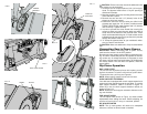
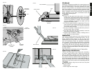
1. Locate the pin and opening on fence rails, as shown in
Figure 5. Align the pin with the slot and align the latch
with the opening.
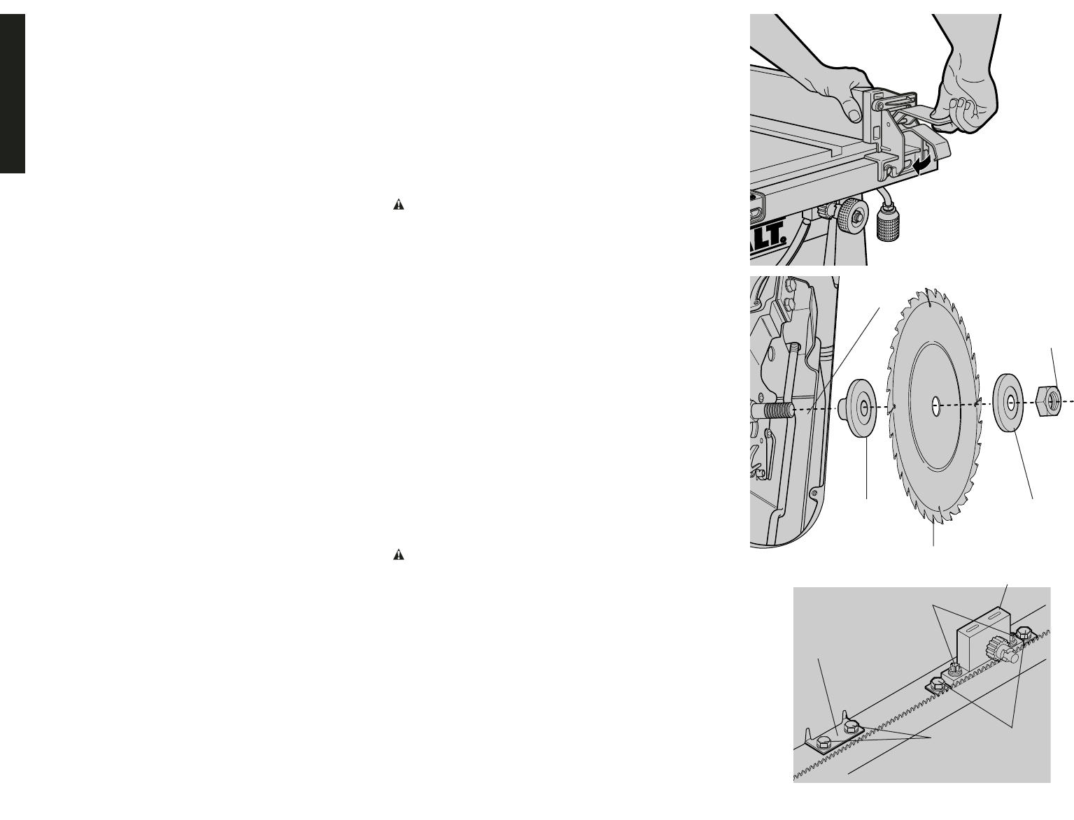
2. Secure the rip fence by snapping the latches onto the
rails as shown in Figure 6. Be sure to snap both latches
in place.
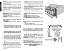
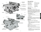
ATTACHING/REPLACING THE BLADE
1. Raise the saw blade arbor to its maximum height by
turning the blade height adjustment wheel clockwise.
2. Remove the arbor nut and flange from the saw arbor by
turning counterclockwise.
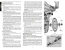
3. Place the saw blade on to the spindle making sure the
teeth of the blade point down at the front of the table.
Assemble the washers and arbor nut to the spindle and
tighten arbor nut as far as possible by hand, making
sure that the saw blade is against the inner washer and
the large washer diameters are against the blade.
Ensure the side of outer washer marked “Blade Side” is
against the blade (see Figure 7). Ensure the spindle and
washers are free from dust and debris.
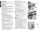
4. To keep the spindle from rotating when tightening the
arbor nut, use the open-ended spindle wrench to secure
the spindle (see Figure 8).
5. Using the arbor wrench, tighten the arbor nut by turn-
ing it clockwise (see Figure 8).
6. NOTE: Different types of blades make different kerfs
(width of cuts). Therefore, it is necessary to check
adjustment of rip fence pointer and blade guard splitter
when changing blades.
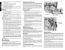
ADJUSTING THE RIP SCALE
1. Unlock the rail lock lever (see Figure 9).
2. Set the blade at 0˚ bevel and move the fence in until it
touches the blade.
3. Lock the rail lock lever.
4. Loosen the rip scale pointer screws (see Figure 16) and
set the rip scale pointer to read zero (0). Retighten the
rip scale pointer screws. The rip scale reads correctly
only when the fence is mounted on the right side of the
blade.
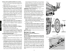
ATTACHING THE BLADE GUARD
1. Raise the saw blade arbor to its maximum height by
turning the blade height adjustment wheel clockwise.
2. Loosen, but do not remove the two bolts shown in
Figure 10.
3. Insert the blade guard as shown in Figure 11, ensuring
the bolts fit into the slots on the blade guard. The edge
of the splitter should protrude below and hook under the
shims. Tighten the bolts. Make sure the splitter is cen-
tered and parallel to the blade by lining up the parts with
a straight edge. If the blade and splitter are not aligned,
loosen, but do not remove the bolts again. Remove the
guard and reinsert it after adjusting the shims. These
shims allow for precision alignment of the blade and
splitter. Tighten the bolts securely. Make sure that there
is clearance between the splitter and the blade, and
that the blade spins freely. If the splitter is tilted relative
to the blade, the splitter plate can be bent until it lines
up correctly.
IMPORTANT: THE GUARD SHOULD BE IN PLACE
FOR ALL POSSIBLE CUTS.
4. Retighten the bolts securely.
WARNING: Before connecting the table saw to the power
source or operating the saw, always inspect the guard and
splitter for proper alignment and clearance with saw blade.
Check alignment after each change of bevel angle.
When properly aligned, the splitter will be in line with the
blade at both table top level, and at the top of the blade.
Check using the straight edge. With power disconnected,
operate the blade tilt and height adjustments through the
extremes of travel and insure the guard clears the blade in all
operations and that the anti-kickback teeth are functioning.
ATTACHING THE THROAT PLATE
1. Align the throat plate as shown in Figure 12, and insert
the tabs on the back of the throat plate into the holes on
the back of the table.
2. Press down on the front of the throat plate to snap it into
place.
3. The throat plate includes four adjustment screws which
raise or lower the throat plate. When properly adjusted,
the front of the throat plate should be flush or slightly
below the surface of the table top and secured in place.
The rear of the throat plate should be flush or slightly
above the table top.
4. Turn the cam lock screw (Detail Fig. 12) clockwise 1/4
turn to lock the throat plate in place.
CAUTION: The throat plate must be in place at all times.
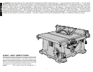
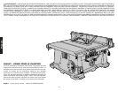
Bench Mounting
TURN OFF AND UNPLUG TABLE SAW
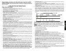
The table saw must be mounted firmly. The mounting sur-
face must have a 15" by 20" opening to allow dust to
escape.
Four holes are provided in the tool’s feet for mounting. We
strongly recommend that these holes be used to anchor the
table saw to your workbench or other stationary rigid frame.
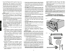
Alternately, to enhance the saw’s portability, it can be
mounted to a piece of wood that can be “C” clamped to your
work surface, stand or Workmate® Workcenter. The
D
EWALT DW7440 Table Saw Stand is designed for use with
this saw, and is available from your local D
EWALT dealer or
service center.
English
FIG. 6
FIG. 7
ARBOR
NUT
OUTER
WASHER
INNER
WASHER
SPINDLE
BLADE
FIG. 7A
10MM HEX BOLTS
REAR
PIVOT
BRACKET
(SAW SHOWN UPSIDE DOWN FOR CLARITY)
TORX HEAD
BOLTS
REAR PINION BEARING ASSEMBLY